Installing the IDE
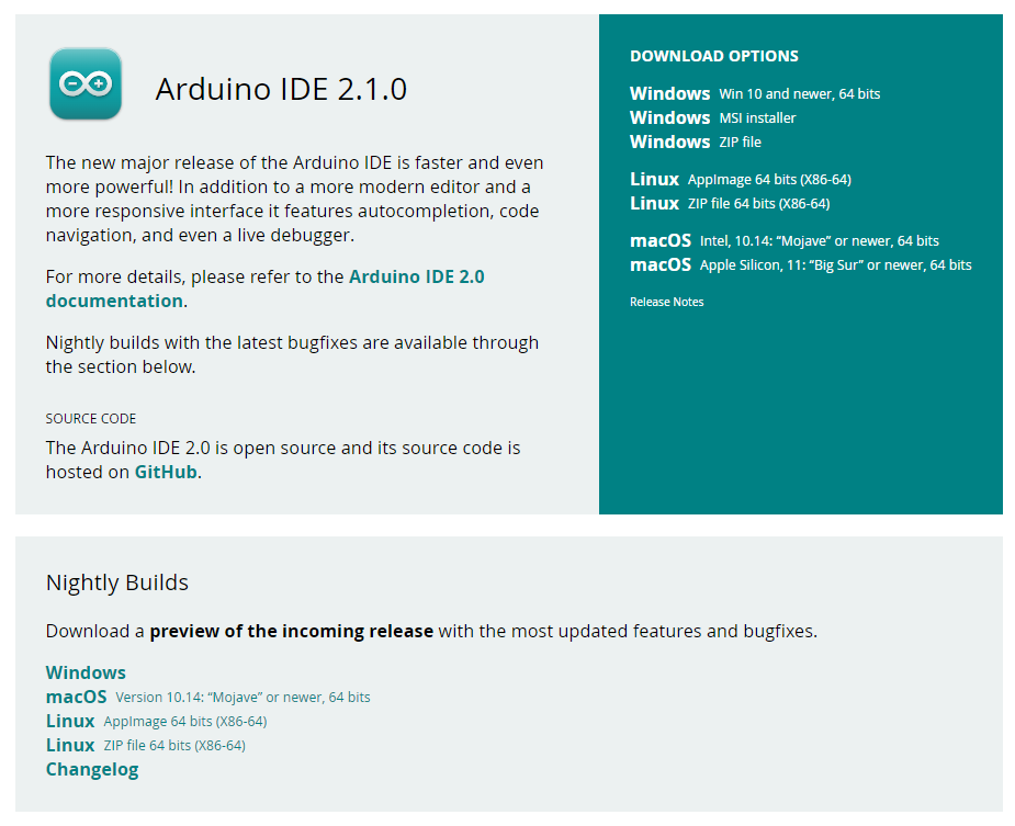
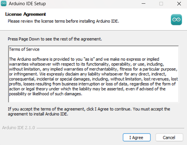
The Arduino IDE can be downloaded online from the Arduino website. It is available for Mac os, Linux, Windows for 32 bit and 64 bit architecture.
You can refer to here for downloading the software.
A microcontroller (microcontroller unit MCU, MC, UC, or μC) is a small computer on a single VLSI integrated circuit (IC) chip. A microcontroller contains one or more CPUs (processor cores), along with memory and programmable input/output peripherals. Program memory in the form of ferroelectric RAM, NOR flash, or OTP ROM is often included on the chip as well as a small amount of RAM. Microcontrollers are designed for embedded applications, as opposed to microprocessors used in personal computers and other general purpose applications, which consist of various discrete chips.
The firm, project, and user community known as Arduino develops and produces single-board microcontrollers and microcontroller kits for the construction of digital devices. The software is distributed under the GNU Lesser General Public Licence (LGPL) or the GNU General Public Licence (GPL), allowing anybody to produce Arduino boards and distribute the programme. The company's hardware products are licenced under a CC BY-SA licence. Commercial Arduino boards are offered on the official website or from accredited distributors.
The ESP32, released in 2016, is an enhanced version of the ESP8266. It includes a dual-core processor, increased memory capacity, and additional features such as Bluetooth connectivity, more GPIO pins, touch sensors, and support for various interfaces (SPI, I2C, UART, etc.). The ESP32 offers better performance and more capabilities compared to the ESP8266.
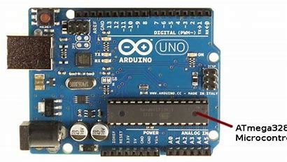
 S.no	                           Name
  1	                          7-12 V Barrel Jack

  2	                          Voltage Regulator

  3	                          16 MHz Crystal Oscillator

  4	                          USB - B Port

  5	                          Reset Button

  6	                          Digital Pins

  7	                          ICSP Pins (SPI can be accessed

                                  from here)

  8	                          ATmega328P microcontroller

  9	                          Analog Pins

  10	                        Serial Port TX RX LEDs

  11	                        USB to UART Conversion IC

  12	                        Built-in LED (connected to pin 13)
What we are going to learn in ESP
The Arduino IDE can be downloaded online from the Arduino website. It is available for Mac os, Linux, Windows for 32 bit and 64 bit architecture.
You can refer to here for downloading the software.
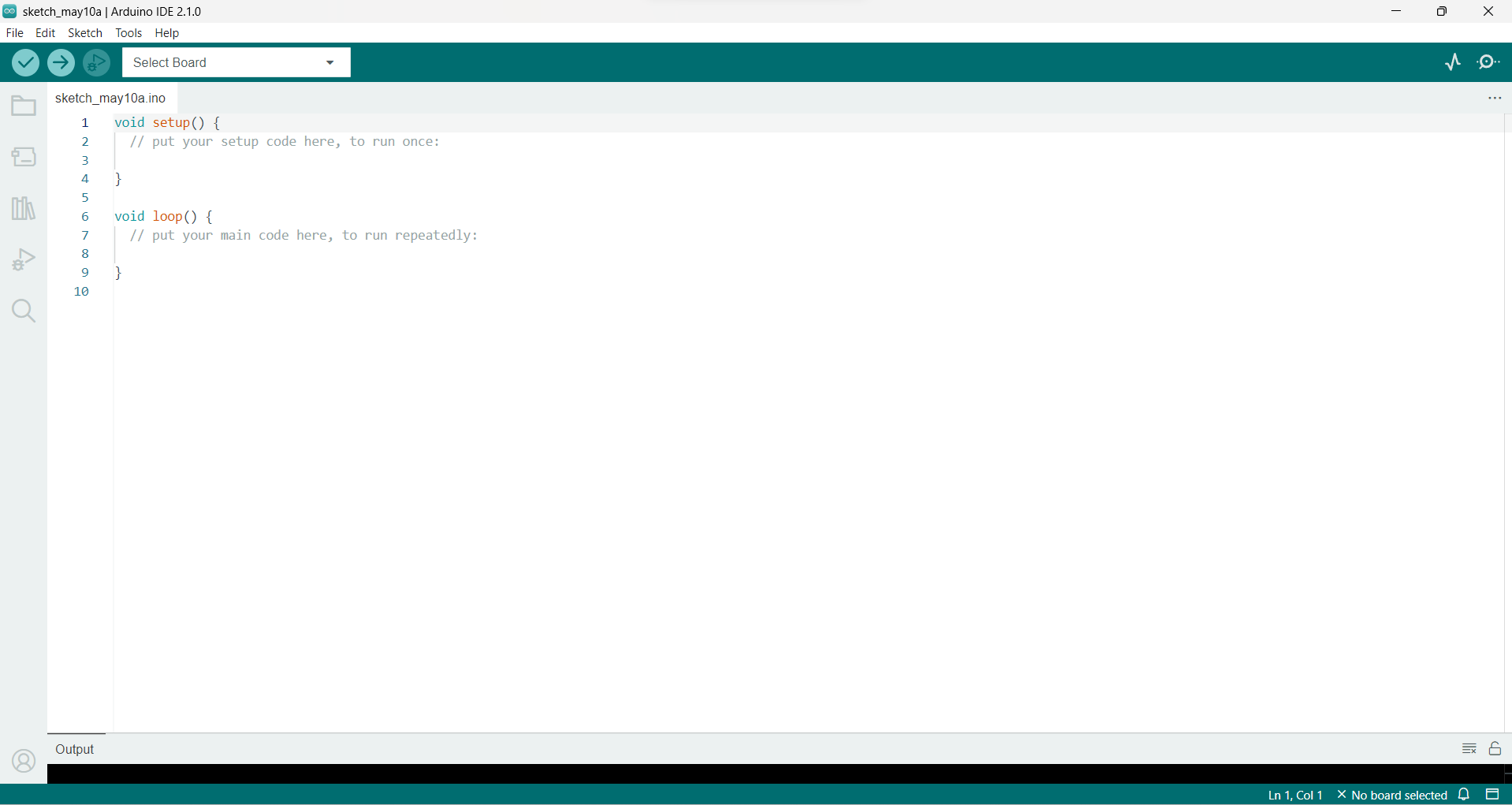
There are some inbuilt function in Arduino that are used to program an Arduino board.
The setup() function is called when a sketch starts. Use it to initialize the variables, pin modes, start using libraries, etc. The setup function will only run once, after each power up or reset of the Arduino board.
void loop()After creating a setup() function, which initializes and sets the initial values, the loop() function does precisely what its name suggests, and loops consecutively, allowing your program to change and respond. Use it to actively control the Arduino board.
digitalRead()This function reads the digital state (either HIGH or LOW) of a specific pin on the Arduino board. It takes one argument, which is the pin number that you want to read. For example, digitalRead(3) will read the state of pin 3.
digitalWrite()This function writes a digital value (either HIGH or LOW) to a specific pin on the Arduino board. It takes two arguments: the pin number that you want to write to and the value you want to write (either HIGH or LOW). For example, digitalWrite(3, HIGH) will set pin 3 to HIGH.
analogRead()This function reads the analog voltage value on a specific analog pin on the Arduino board. It takes one argument, which is the pin number that you want to read. For example, analogRead(A0) will read the voltage value on pin A0.
analogWrite()This function writes an analog value (a value between 0 and 255) to a specific pin on the Arduino board. It takes two arguments: the pin number that you want to write to and the value you want to write (between 0 and 255). Not all pins on an Arduino board support analogWrite. Only the ones with a "~" symbol next to the pin number are capable of analog output. For example, analogWrite(9, 128) will set pin 9 to output a voltage of 50% of the maximum voltage (5V on most Arduinos).
pinMode()This function sets the mode of a specific pin on the Arduino board. It takes two arguments: the pin number that you want to set and the mode you want to set it to (either INPUT or OUTPUT). For example, pinMode(3, INPUT) will set pin 3 to INPUT mode.
delay()This function causes the Arduino board to pause for a specified number of milliseconds. It takes one argument, which is the number of milliseconds to pause. For example, delay(1000) will pause the board for 1 second.
Serial.begin()This function initializes serial communication on the Arduino board. It takes one argument, which is the baud rate (the rate at which data is transmitted) that you want to use for serial communication. For example, Serial.begin(9600) will initialize serial communication at a baud rate of 9600.
Serial.print()This function sends data over serial communication. It takes one or more arguments, which are the values that you want to send. For example, Serial.print("Hello World") will send the string "Hello World" over serial communication. You can also use Serial.println() to send the data followed by a newline character.

A sketch in Arduino is a program that runs on the microcontroller inside the Arduino board. It is written in the Arduino programming language, which is based on C and C++. A sketch typically consists of two functions: setup() and loop().
setup(): This function is called once when the Arduino board is first powered on or reset. It is used to initialize any hardware components that the sketch will use, such as setting pin modes and initializing communication protocols. Any code in setup() will only be executed once.
loop(): This function is called repeatedly after setup() has completed. It is used to define the main logic of the sketch, which will be executed continuously as long as the board is powered on or not reset. Any code in loop() will be executed over and over again, until the board is powered off or reset.
A typical Arduino sketch will have a combination of both setup() and loop() functions, with the setup() function used to configure hardware components and the loop() function used to run the main logic of the sketch.
Here is an example of a simple Arduino sketch that reads the state of a button connected to pin 2 and turns on an LED connected to pin 13 when the button is pressed:
        void setup() {
          pinMode(2, INPUT);   // set pin 2 as input
          pinMode(13, OUTPUT); // set pin 13 as output
        }
        void loop() {
          int buttonState = digitalRead(2); // read state of button on pin 2

          if (buttonState == HIGH) { // if button is pressed
            digitalWrite(13, HIGH); // turn on LED on pin 13
          } else { // if button is not pressed
            digitalWrite(13, LOW); // turn off LED on pin 13
          }}
In this sketch, the setup() function sets pin 2 as an input and pin 13 as an output. In the loop() function, the state of pin 2 is read using digitalRead() and stored in a variable called buttonState. If the button is pressed (which sets pin 2 to HIGH), the LED on pin 13 is turned on using digitalWrite(). If the button is not pressed (which sets pin 2 to LOW), the LED on pin 13 is turned off using digitalWrite(). The loop() function runs continuously, so the sketch will keep checking the state of the button and turning the LED on and off as appropriate.
Baud rate is a term used to describe the speed of data transmission between two devices. In the context of Arduino, the baud rate refers to the rate at which data is transmitted or received over the serial communication port.
The Arduino board has a built-in serial communication port, which allows it to communicate with other devices or computers using the Serial library. The Serial library provides functions for sending and receiving data over the serial port, and it uses a baud rate to determine the speed of the data transfer.
The baud rate is measured in bits per second (bps) and it determines how fast data is transmitted over the serial port. The most common baud rates used in Arduino are 9600, 19200, 38400, 57600, and 115200 bps.
The baud rate used for serial communication must be set to the same value on both the Arduino board and the receiving device. If the baud rates are not the same, the data may be transmitted at the wrong speed and the receiving device may not be able to correctly interpret the data.
To set the baud rate in an Arduino sketch, you can use the Serial.begin() function, which takes a single argument specifying the baud rate. For example, to set the baud rate to 9600 bps, you would call the Serial.begin(9600) function in the setup() function of your sketch.
    void setup() {
      Serial.begin(9600); // set baud rate to 9600 bps
    }
    void loop() {
      // send and receive data using Serial library functions
    }
Analog output refers to the ability of the Arduino board to generate a variable voltage on an output pin that can be set to any value within a specific range. This is achieved using the Pulse Width Modulation (PWM) technique, which essentially involves rapidly turning the output pin on and off in a controlled pattern to simulate a varying voltage level.
With analog output, you can generate a signal that has a smooth, continuous range of values rather than just two discrete states (high and low) like with digital output. This makes it ideal for controlling devices that require a varying voltage, such as LEDs, motors, and audio speakers.
To output an analog voltage on an Arduino board, you can use the analogWrite() function. This function takes two arguments: the first is the pin number to which the output signal is to be sent, and the second is the value of the signal which can be a number between 0 (0V) and 255 (5V).
Here's an example of using the analogWrite() function to output an analog signal to control the brightness of an LED connected to pin 9:
  void setup() {
    pinMode(9, OUTPUT); // set pin 9 as output
  }
  void loop() {
    analogWrite(9, 127); // output an analog signal with a value of 127 (50% of maximum)
    delay(1000); // wait for 1 second
    analogWrite(9, 255); // output an analog signal with a value of 255 (100% of maximum)
    delay(1000); // wait for 1 second
    analogWrite(9, 0); // output an analog signal with a value of 0 (0% of maximum)
    delay(1000); // wait for 1 second
  }
Digital output is the ability of an Arduino board to output a binary signal that can only be in one of two states: high or low. High corresponds to a voltage of 5 volts, and low corresponds to a voltage of 0 volts.
To output a digital signal, you need to configure a pin on the Arduino board as an output pin using the pinMode() function and then set its state to either HIGH or LOW using the digitalWrite() function.
Here's an example of using digital output to turn an LED connected to pin 9 on and off:
    void setup() {
      pinMode(9, OUTPUT); // set pin 9 as an output pin
    }
    void loop() {
      digitalWrite(9, HIGH); // turn on the LED by setting pin 9 to HIGH
      delay(1000); // wait for 1 second
      digitalWrite(9, LOW); // turn off the LED by setting pin 9 to LOW
      delay(1000); // wait for 1 second
    }
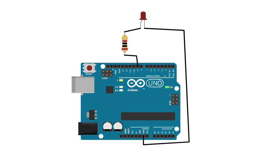
Working with LEDs in Arduino is a great way to get started with basic digital output. LEDs (Light Emitting Diodes) are small, low-power, and inexpensive devices that emit light when current flows through them. They are commonly used in electronics projects to indicate the state of a circuit or to provide visual feedback to the user.
To get started working with LEDs in Arduino, you'll need an LED, a current limiting resistor, and a few jumper wires to connect everything together. Here's an example of wiring up an LED to an Arduino board:
Here's an example program:
      void setup() {
        pinMode(9, OUTPUT); // set pin 9 as an output pin
      }
      void loop() {
        digitalWrite(9, HIGH); // turn on the LED by setting pin 9 to HIGH
        delay(1000); // wait for 1 second
        digitalWrite(9, LOW); // turn off the LED by setting pin 9 to LOW
        delay(1000); // wait for 1 second
      }
In this example, the digitalWrite() function is used to turn an LED connected to pin 9 on and off. The LED is turned on by setting the pin 9 to HIGH, and turned off by setting the pin 9 to LOW. The delay() function is used to create a pause between turning the LED on and off.
NOTE:Note that it's important to use a resistor when working with LEDs to prevent them from burning out due to excess current. The value of the resistor should be chosen based on the characteristics of the LED and the voltage applied to it, to ensure that the LED operates within its safe range of current and voltage.
In this example, we're using analogRead() to read the value from an analog input pin (in this case, pin A0). The function returns a value between 0 and 1023, which corresponds to the voltage on the pin, scaled to a 10-bit value (since the Arduino's analog-to-digital converter has 10 bits of resolution).
We're then using Serial.println() to print the sensor value to the serial monitor. This allows us to see the value of the sensor in real-time as the program runs.
The delay() function is used to create a pause between readings, so that the program doesn't read the sensor value too quickly and overload the serial output.
This is a simple example, but analogRead() can be used in a wide variety of applications where you need to measure an analog voltage or sensor value.
      void setup() {
        Serial.begin(9600); // initialize serial communication at 9600 bits per second
      }
      void loop() {
        int sensorValue = analogRead(A0); // read the value from analog input pin A0
        Serial.println(sensorValue); // print the sensor value to the serial monitor
        delay(1000); // wait for 1 second
      }
Getting data from a sensor in Arduino typically involves using one of the input pins to read the voltage or signal produced by the sensor, and then using a function like analogRead() or digitalRead() to convert the voltage or signal into a numerical value that can be used by the program.
    void setup() {
      Serial.begin(9600); // initialize serial communication at 9600 bits per second
    }
    void loop() {
      int sensorValue = analogRead(A0); // read the value from analog input pin A0
      Serial.println(sensorValue); // print the sensor value to the serial monitor
      delay(1000); // wait for 1 second
    }
We're using an analog sensor (in this case, a potentiometer) connected to analog input pin A0 and then using analogRead() to read the voltage produced by the potentiometer, which produces a value between 0 and 1023. We're then using the map() function to convert this value into a range between 0 and 255, which is more convenient for working with other functions like analogWrite(). Finally, we're using Serial.println() to print the mapped value to the serial monitor, so we can see the sensor value in real-time as the program runs.
Note that different sensors may require different methods of reading data, depending on their electrical characteristics and the type of signal they produce. For example, some sensors may produce a digital signal that can be read using digitalRead(), while others may require more complex analog or digital signal conditioning to produce a usable output.
In Arduino, variables are used to store data that can be used and manipulated by the program. There are several data types available for use in Arduino, each with different properties and uses. Here are some of the most commonly used data types in Arduino:
int: A 16-bit signed integer, which can store values between -32768 and 32767.
unsigned int: A 16-bit unsigned integer, which can store values between 0 and 65535.
long: A 32-bit signed integer, which can store values between -2147483648 and 2147483647.
unsigned long: A 32-bit unsigned integer, which can store values between 0 and 4294967295.
float: A floating-point number, which can store decimal values with up to 6-7 digits of precision.
double: A double-precision floating-point number, which can store decimal values with up to 15 digits of precision.
boolean: A boolean value, which can store either true or false.
char: A single character, which can store any ASCII character.
The Communication port is a built-in USB interface that is available on most Arduino boards. It allows users to upload code to the Arduino board, communicate with the board over a serial port, and power the board using a USB cable. The USB programming port is also used to configure the bootloader and update the firmware on the board.
When a USB cable is connected to the programming port on an Arduino board, it provides power to the board and establishes a serial connection between the board and the computer. This serial connection can be used for debugging, sending and receiving data, and programming the board. The Arduino IDE includes a serial monitor that allows users to send and receive data to and from the board over the serial port.
To use the Communication port, users need to select the appropriate board and serial port in the Arduino IDE. They can then upload their code to the board using the "Upload" button in the IDE. The Arduino IDE sends the compiled code to the board over the serial port, where it is stored in the board's flash memory. Once the code is uploaded, the board can be disconnected from the computer and powered using an external power source.
The Communication port is an essential feature of Arduino boards, as it allows users to easily program and communicate with the board without requiring additional hardware. By using the USB programming port, users can quickly prototype their projects and test their code, making the Arduino platform an ideal choice for hobbyists, students, and professionals alike.
Importance of Communication portCommunication ports are an important aspect of Arduino programming as they allow the Arduino to exchange data with other devices, including computers, sensors, and other microcontrollers. There are several communication ports available on Arduino boards, including Serial, I2C, SPI, and UART.
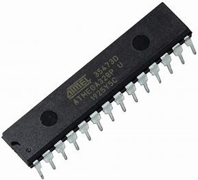
The Atmega328 is a microcontroller chip that is used in many Arduino boards, including the popular Arduino Uno. It is a 28-pin chip that contains a central processing unit (CPU), flash memory, random-access memory (RAM), and various input/output (I/O) pins.
The Atmega328 chip runs at a clock speed of 16 MHz and has 32 KB of flash memory, 2 KB of SRAM, and 1 KB of electrically erasable programmable read-only memory (EEPROM). The flash memory is used to store the Arduino code, while the SRAM is used for temporary data storage during program execution. The EEPROM is a non-volatile memory that can be used to store data that needs to be retained even when the power is turned off.
The Atmega328 chip has a wide range of I/O pins that can be used to connect various sensors, actuators, and other peripheral devices. It has 14 digital I/O pins, which can be used as inputs or outputs, and 6 analog input pins, which can be used to read analog signals from sensors. The chip also has several other pins, such as the reset pin, crystal oscillator pins, and power pins, which are used for various functions.
The Atmega328 chip is programmed using the Arduino Integrated Development Environment (IDE), which provides a user-friendly interface for writing, compiling, and uploading code to the chip. The Arduino IDE includes a large library of pre-written functions and examples, which makes it easy for users to get started with the platform.
In conclusion, the Atmega328 chip is a key component of many Arduino boards, and it provides a powerful and flexible platform for building a wide range of projects. Its high clock speed, ample memory, and versatile I/O pins make it an ideal choice for hobbyists, students, and professionals who want to create interactive electronics projects using the Arduino platform.
In Arduino programming, the delay() function is used to pause the execution of the program for a specified amount of time. The delay() function takes an integer parameter, which represents the number of milliseconds to pause the program. For example, the following code will pause the program for 1 second (1000 milliseconds).
delay 1000; //Pause the program for 1 seconds
The delay() function is useful in many scenarios, such as controlling the timing of a sequence of events, creating a delay between sensor readings, or controlling the blinking of an LED. For example, the following code will blink an LED connected to pin 13 on an Arduino board.
    void setup() {
      pinMode(13, OUTPUT); // Set pin 13 as an output
    }
    void loop() {
      digitalWrite(13, HIGH); // Turn the LED on
     delay(1000); // Pause the program for 1 second
      digitalWrite(13, LOW); // Turn the LED off
      delay(1000); // Pause the program for 1 second
    }
In this example, the setup() function sets pin 13 as an output, which is used to control the LED. The loop() function then turns the LED on, pauses the program for 1 second using the delay() function, turns the LED off, and pauses the program for another second. This sequence of events is repeated indefinitely, resulting in the LED blinking on and off every second.
It is important to note that the delay() function pauses the entire program, including any other events or tasks that may be running. If the program needs to perform other tasks while waiting for the delay() function to complete, a different approach, such as using a timer or interrupt, may be necessary.
MillisIn Arduino programming, the millis() function is used to obtain the number of milliseconds that have elapsed since the program started running. The millis() function returns an unsigned long integer value, which can be used to track time or to create timing-based events in the program.
Unlike the delay() function, which pauses the program for a specified amount of time, the millis() function allows the program to continue running while still keeping track of time. This is achieved by using a hardware timer that runs independently of the main program loop.
      const int LED_PIN = 13;
      const unsigned long BLINK_INTERVAL = 1000; // Blink the LED every second
      unsigned long previousMillis = 0;
      void setup() {
        pinMode(LED_PIN, OUTPUT); // Set the LED pin as an output
      }
      void loop() {
        unsigned long currentMillis = millis(); // Get the current time
        if (currentMillis - previousMillis >= BLINK_INTERVAL) { // Check if it's time to blink the LED
          previousMillis = currentMillis; // Save the current time
          digitalWrite(LED_PIN, !digitalRead(LED_PIN)); // Toggle the LED state
        }
      }
In this example, the program sets up a constant LED_PIN to control an LED and sets the BLINK_INTERVAL to 1000 milliseconds (1 second). The program also creates a previousMillis variable to store the time of the last blink.
In the loop() function, the program retrieves the current time using the millis() function and checks if it has been more than BLINK_INTERVAL milliseconds since the last blink. If it has, the program toggles the state of the LED using digitalWrite(), saves the current time to previousMillis, and waits for the next cycle.
By using the millis() function and a timing-based approach, the program can continue to run other tasks while still keeping track of time and creating timed events. This is a more efficient and flexible approach than using the delay() function, which would pause the entire program for a specified amount of time.
Difference between delay and millis
When you use the delay() function, the program pauses for the specified amount of time before moving on to the next line of code. During this time, the program is not able to perform any other tasks. This can cause issues if you have time-critical tasks that need to be performed or if you want the program to be responsive to user input.
On the other hand, the millis() function allows the program to continue running while still keeping track of time. This is achieved by using a hardware timer that runs independently of the main program loop. With millis(), you can create timing-based events or delays without pausing the program execution.
        void setup() {
          pinMode(LED_PIN, OUTPUT);
        }
        void loop() {
          digitalWrite(LED_PIN, HIGH);
          delay(1000); // Pause the program for 1 second
          digitalWrite(LED_PIN, LOW);
          delay(1000); // Pause the program for 1 second
          unsigned long currentMillis = millis(); // Get the current time
          if (currentMillis % 2000 < 1000) { // Blink the LED every 2 seconds
            digitalWrite(LED_PIN, HIGH);
          } else {
            digitalWrite(LED_PIN, LOW);
          }
        }
In this example, the program blinks an LED using both delay() and millis(). The first part of the loop uses delay() to pause the program execution for 1 second before toggling the LED state. This means that the program cannot perform any other tasks during this time.
The second part of the loop uses millis() to blink the LED every 2 seconds without pausing the program execution. This is achieved by checking the current time and toggling the LED state based on the elapsed time. This allows the program to perform other tasks while still keeping track of time and creating timed events.
In Arduino programming, loops are used to execute a set of instructions repeatedly. There are two main types of loops in Arduino: for and while.
The for loop is used when you know how many times you want to execute a set of instructions. The general syntax for a for loop in Arduino is
     for (initialization; condition; increment) {
      // instructions to execute
    }
Here's an example that blinks an LED 10 times using a for loop:
    void setup() {
      pinMode(LED_PIN, OUTPUT);
    }
    void loop() {
      for (int i = 0; i < 10; i++) {
        digitalWrite(LED_PIN, HIGH);
        delay(500);
        digitalWrite(LED_PIN, LOW);
        delay(500);
      }}
In this example, the for loop runs 10 times and blinks an LED on and off with a 500ms delay between each state change.
The while loop is used when you want to execute a set of instructions repeatedly until a certain condition is met. The general syntax for a while loop in Arduino is
Here's an example that reads a sensor and prints the value to the serial monitor using a while loop.
    void setup() {
      Serial.begin(9600);
    }
    void loop() {
      int sensorValue = analogRead(A0);
      while (sensorValue < 500) {
        Serial.println("Sensor value is too low!");
        delay(1000);
        sensorValue = analogRead(A0);
      }
      Serial.println("Sensor value is okay.");
      delay(1000);
    }
In this example, the program reads a sensor value and enters a while loop if the value is less than 500. Inside the loop, it prints a message to the serial monitor and waits for 1 second before reading the sensor value again. Once the sensor value is above 500, the loop exits and the program continues to print a different message to the serial monitor with a 1 second delay. This process repeats indefinitely.
In Arduino programming, a condition is a logical statement that is evaluated to either true or false. Conditions are typically used in control structures like if statements and loops to make decisions about which set of instructions to execute.
Here's an example that uses a condition to determine whether an LED should be turned on or off.
      void setup() {
        pinMode(LED_PIN, OUTPUT);
      }

      void loop() {
        int sensorValue = analogRead(A0);
        if (sensorValue > 500) {
          digitalWrite(LED_PIN, HIGH);
        } else {
          digitalWrite(LED_PIN, LOW);
        }
      }
In this example, the program reads a sensor value and checks if it is greater than 500. If the condition is true, the LED connected to pin 13 is turned on using digitalWrite(). If the condition is false, the LED is turned off.
Conditions can also be combined using logical operators like && (AND) and || (OR). Here's an example that uses a condition with an AND operator to check if two sensor values are both greater than a certain threshold.
      void loop() {
        int sensorValue1 = analogRead(A0);
        int sensorValue2 = analogRead(A1);
        if (sensorValue1 > 500 && sensorValue2 > 500) {
          Serial.println("Both sensors are above the threshold.");
        }
      }
In this example, the program reads two sensor values and checks if both are greater than 500 using an AND operator. If the condition is true, a message is printed to the serial monitor.