The ESP32 and ESP8266 are popular series of low-cost, low-power, and highly versatile Wi-Fi and Bluetooth-enabled microcontrollers developed by Espressif Systems. These microcontrollers are widely used in various Internet of Things (IoT) applications.
The ESP8266 was the first chip released by Espressif Systems in 2014. It gained significant popularity due to its affordability, ease of use, and compatibility with Arduino development boards. The ESP8266 features a 32-bit Tensilica processor, built-in Wi-Fi connectivity, and sufficient memory to run applications.
The ESP32, released in 2016, is an enhanced version of the ESP8266. It includes a dual-core processor, increased memory capacity, and additional features such as Bluetooth connectivity, more GPIO pins, touch sensors, and support for various interfaces (SPI, I2C, UART, etc.). The ESP32 offers better performance and more capabilities compared to the ESP8266.
Both the ESP8266 and ESP32 have gained popularity in the maker and IoT communities due to their affordability, ease of use, extensive documentation, and large developer community. They can be programmed using the Arduino IDE, MicroPython, or the Espressif's native development framework called ESP-IDF. These microcontrollers are widely used for building IoT devices, home automation systems, wireless sensor networks, and various other projects that require Wi-Fi or Bluetooth connectivity.
ESP32 is a series of low-cost, low-power system-on-chip microcontrollers with integrated Wi-Fi and Bluetooth capabilities. It is designed and manufactured by Espressif Systems, a company based in Shanghai, China.
The ESP32 microcontroller is a successor to the popular ESP8266 microcontroller and features a dual-core processor with more memory and I/O capabilities. It is widely used in the Internet of Things (IoT) applications, including home automation, smart devices, wearables, and robotics.
Some of the key features of the ESP32 include:
Dual-core 32-bit processor
Wi-Fi (802.11 b/g/n) and Bluetooth (BLE) connectivity
Multiple GPIO pins and interfaces, including I2C, SPI, UART, ADC, and DAC
Capacitive touch sensors
Support for different operating systems, including FreeRTOS, Zephyr, and Arduino
Low power consumption with multiple power modes
Integrated security features, including support for SSL/TLS and WPA2-Enterprise encryption
The ESP32 can be programmed using various development environments, including the Arduino IDE, Espressif's own ESP-IDF, and MicroPython. It is a versatile and powerful microcontroller that is widely used in the development of IoT projects.
What is ESP8266
ESP8266 is a low-cost, low-power system-on-chip (SoC) microcontroller with integrated Wi-Fi capabilities. It is designed and manufactured by Espressif Systems, a company based in Shanghai, China.
The ESP8266 microcontroller became popular due to its low cost, small size, and built-in Wi-Fi connectivity, making it suitable for Internet of Things (IoT) applications such as home automation, sensor networks, and smart devices.
The ESP8266 microcontroller has a single-core processor with 32-bit RISC architecture and features multiple input/output (I/O) interfaces, including General Purpose Input/Output (GPIO), Inter-Integrated Circuit (I2C), Serial Peripheral Interface (SPI), Universal Asynchronous Receiver/Transmitter (UART), and Analog-to-Digital Converter (ADC).
Some of the key features of the ESP8266 include:
Low power consumption with multiple power modes
Integrated Wi-Fi connectivity with support for 802.11 b/g/n
Multiple GPIO pins and interfaces, including I2C, SPI, UART, ADC, and DAC
Support for different operating systems, including FreeRTOS and NodeMCU
Integrated security features, including support for SSL/TLS and WPA2-Enterprise encryption
The ESP8266 can be programmed using various development environments, including the Arduino IDE, NodeMCU Lua, and MicroPython. It is a versatile and popular microcontroller that has helped to drive the growth of the IoT industry.
How They are different from each Other
Processor:
ESP8266 has a single-core processor with 32-bit RISC architecture while ESP32 has a dual-core processor with 32-bit RISC-V architecture. ESP32 has more processing power than ESP8266 and can handle more complex tasks.
Memory:
ESP32 has more memory than ESP8266, including more RAM and Flash memory. This means that ESP32 can handle larger programs and store more data than ESP8266.
Input/Output Interfaces:
ESP32 has more input/output (I/O) interfaces than ESP8266, including I2S, I2C, SPI, UART, ADC, and DAC. ESP8266 also has multiple I/O interfaces but not as many as ESP32.
Wi-Fi Connectivity:
Both microcontrollers have built-in Wi-Fi connectivity, but ESP32 has more advanced Wi-Fi features, including support for both 2.4GHz and 5GHz Wi-Fi bands, and more security protocols. ESP8266 only supports 2.4GHz Wi-Fi and fewer security protocols.
Bluetooth Connectivity:
ESP32 has built-in Bluetooth connectivity, while ESP8266 does not.
Power Consumption:
ESP32 has more power modes than ESP8266, allowing it to consume less power when running on battery or low-power applications. However, ESP8266 has a low-power deep-sleep mode that allows it to consume very little power.
Cost:
ESP8266 is generally cheaper than ESP32 due to its simpler design and fewer features. Overall, both ESP8266 and ESP32 are powerful and versatile microcontrollers that can be used for a wide range of IoT applications. The choice between the two depends on the specific requirements of the project, including processing power, memory, connectivity, and power consumption.
How They are different from Arduino
ESP and Arduino are two different platforms for building electronic projects. The main differences between them are:
Microcontroller: :
Arduino boards are based on Atmel microcontrollers such as the ATmega328P, while ESP boards are based on the Espressif Systems ESP8266 or ESP32 microcontrollers. The ESP8266 and ESP32 have built-in Wi-Fi capabilities, making them ideal for Internet of Things (IoT) applications.
Programming Language: :
Arduino uses a simplified version of C++ programming language and has its own Integrated Development Environment (IDE). On the other hand, ESP boards can be programmed using the Arduino IDE as well as the Espressif's ESP-IDF which provides low-level access to the ESP microcontroller.
Connectivity: :
ESP boards have built-in Wi-Fi capabilities, making it easier to connect to the internet and other Wi-Fi enabled devices. Arduino boards require additional hardware, such as a Wi-Fi shield, to connect to the internet or other devices.
Processing Power: :
ESP boards are generally more powerful than Arduino boards. The ESP32, for example, has two cores and can run at up to 240 MHz, while the Arduino Uno runs at 16 MHz with one core. This difference in processing power makes ESP boards better suited for complex applications.
Price: :
ESP boards are generally cheaper than Arduino boards. This is because the ESP microcontrollers are cheaper than the Atmel microcontrollers used in Arduino boards. However, the cost of the board also depends on the specific model and features.
Installing Board of ESP32 and ESP8266
Install the Latest Arduino IDE
Before you can install the board of ESP32 and ESP8266 in the Arduino IDE, you need to download and install the latest version of the Arduino IDE software. You can download it from the official Arduino website.
Add Board Manager URLs
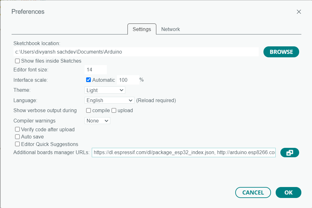
The next step is to add the board manager URLs for ESP32 and ESP8266. To do this, open the Arduino IDE and go to File > Preferences. In the "Additional Boards Manager URLs" field, enter the following URLs:
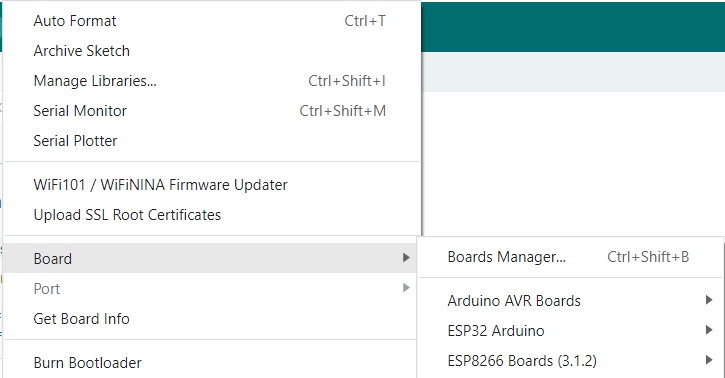
After adding the board manager URLs, you need to install the board package. To do this, go to Tools > Board > Boards Manager. In the Boards Manager window, search for "ESP32" or "ESP8266" and install the package.
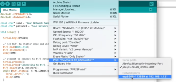
Select Board and Port
Once the board package is installed, you can select the board and port for your project. Go to Tools > Board and select the board you want to use, such as "ESP32 Dev Module" or "NodeMCU 1.0 (ESP-12E Module)" for ESP8266. Then, go to Tools > Port and select the port your board is connected to.
Getting Data in Serial Monitor
The serial monitor is a very useful tool that is included in the Integrated Development Environment (IDE). It allows you to view and send data to and from your ESP board via a serial connection. This can be very helpful when you are trying to debug your code or troubleshoot any problems that you are having.
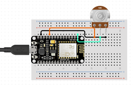
To get data in the serial monitor, you need to establish a serial communication between the board and the computer. Serial communication is a way to exchange information between the two devices through a serial interface, typically via a USB cable. Connect the board to your computer via a USB cable.
Open the IDE and select the correct board and serial port from the Tools menu.
In your sketch, use the Serial.begin() function to initialize the serial communication at a specified baud rate. For example, Serial.begin(9600) initializes the serial communication at a baud rate of 9600 bits per second.
In your code, use the Serial.println() function to send data to the serial port. For example, Serial.println("Hello World!") sends the message "Hello World!" to the serial port.
Open the serial monitor by clicking on the serial monitor icon on the top right corner of the IDE or by selecting Serial Monitor from the Tools menu.
Set the baud rate in the serial monitor to match the baud rate you set in your code using the Serial.begin() function.
You should now see the data sent from the board in the serial monitor. You can also send data from the serial monitor to the board by typing in the text box at the top of the serial monitor and clicking the Send button.
int potpin = A0;
void setup() {
Serial.begin(9600);
pinMode(potpin,INPUT);
}
void loop() {
int val = analogRead(potpin);
Serial.print("Potentiometer Value is : ");
Serial.println(val);
}
Turning on the Hotspots
To turn on the hotspot on an ESP8266, you need to configure it as an access point and start the Wi-Fi server.
In the code above, the WiFi.softAP() function sets up the ESP8266 as an access point with the specified SSID and password. The WiFi.softAPIP() function returns the IP address of the access point.
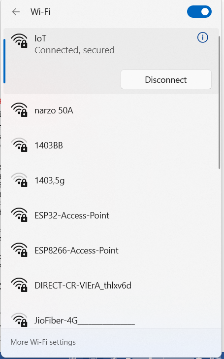
After uploading this code to your ESP8266, you should be able to find the ESP8266's Wi-Fi hotspot with the SSID "ESP8266-Access-Point" and connect to it with the password "123456789". Note that the ESP8266 hotspot has a default IP address of 192.168.4.1, which you can use to connect to the ESP8266 through a browser or other means.
To turn on the hotspot on an ESP32, you need to configure the ESP32 as an access point and start the Wi-Fi server.
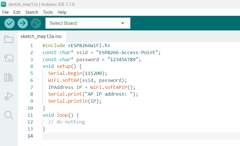
        #include <WiFi.h>
        const char* ssid = "ESP32-Access-Point";
        const char* password = "123456789"; //you can change the ssid an d password
        void setup() {
          Serial.begin(115200);
          WiFi.softAP(ssid, password);
          IPAddress IP = WiFi.softAPIP();
          Serial.print("AP IP address: ");
          Serial.println(IP);
        }
        void loop() {
        }
After uploading this code to your ESP32, you should be able to find the ESP32's Wi-Fi hotspot with the SSID "ESP32-Access-Point" and connect to it with the password "123456789". Note that the ESP32 hotspot has a default IP address of 192.168.4.1
Control via Hotspot
Controlling an ESP32 LED via a hotspot involves creating a web server on the ESP32 and hosting a web page that allows you to turn the LED on and off using a button on the webpage. Here are the general steps to achieve this:
Set up the ESP32 and connect it to your Wi-Fi hotspot.
Create a web server on the ESP32 using the built-in WiFi library in Arduino IDE.
Define a web page that has a button that sends an HTTP request to the server to turn the LED on or off.
Set up the pin mode of the LED and the function that controls the LED.
In the web server code, check for incoming HTTP requests and handle them. If a request is received to turn on or off the LED, call the appropriate function to control the LED.
Upload the code to the ESP32 and open the webpage on a device connected to the same hotspot as the ESP32.
Click on the button on the webpage to turn the LED on or off.
    #include <WiFi.h>
    const char* ssid = "YourSSID";
    const char* password = "YourPassword";
    WiFiServer server(80);
    const int ledPin = 0; // change this to the LED pin you're using
    void setup() {
      pinMode(ledPin, OUTPUT);
      Serial.begin(115200);
      // Connect to Wi-Fi network
      Serial.print("Connecting to ");
      Serial.println(ssid);
      WiFi.begin(ssid, password);
      while (WiFi.status() != WL_CONNECTED) {
        delay(1000);
        Serial.println("Connecting to WiFi...");
      }
      // Start the server
      server.begin();
      Serial.println("Server started");
      // Print the IP address
      Serial.print("IP address: ");
      Serial.println(WiFi.localIP());
    }
    void loop() {
      // Listen for incoming clients
      WiFiClient client = server.available();
      if (client) {
        Serial.println("New client connected");
        String request = client.readStringUntil('\r');
        Serial.println(request);
        client.flush();
        // Check if the client requested the LED on or off
        if (request.indexOf("/led=on") != -1) {
          digitalWrite(ledPin, HIGH);
        } else if (request.indexOf("/led=off") != -1) {
          digitalWrite(ledPin, LOW);
        }
        // Send a response back to the client
        client.println("HTTP/1.1 200 OK");
        client.println("Content-Type: text/html");
        client.println("");
        client.println("<!DOCTYPE HTML>");
        client.println("<html>");
        client.println("<body>");
        client.println("<h1>ESP32 LED Control</h1>");
        client.println("<p>Click <a href=\"/led=on\">here</a> to turn the LED on</p>");
        client.println("<p>Click <a href=\"/led=off\">here</a> to turn the LED off</p>");
        client.println("</body>");
        client.println("</html>");
        delay(1);
        Serial.println("Client disconnected");
      }}}
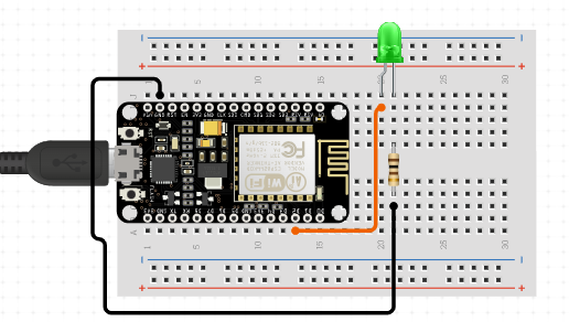
Note that this is just a simple example to get you started, and you'll likely need to modify it to suit your specific needs. You'll also need to connect an LED to the ESP32 and update the ledPin variable to reflect the pin you're using. Additionally, you'll need to replace YourSSID and YourPassword with the SSID and password for your Wi-Fi hotspot.2 .
Note that the specific implementation details will depend on your specific setup and requirements. There are also many resources available online that provide detailed tutorials on how to control an ESP32 LED via a hotspot, which may be helpful in getting started.
To control an ESP8266 LED via a hotspot, you need to follow these basic steps:
Set up the ESP8266 as an access point (AP) and create a hotspot. You can use the ESP8266WiFi library to configure the ESP8266 as an AP and set up the hotspot. You need to define the SSID and password for the hotspot.
Create a webpage to control the LED. You can use HTML, CSS, and JavaScript to create a simple webpage with a button to turn the LED on and off. You can use AJAX to send an HTTP request to the ESP8266 when the button is clicked.
Configure the ESP8266 to handle HTTP requests. You can use the ESP8266WebServer library to handle HTTP requests. You need to define a handler function that listens for the HTTP request from the webpage and turns the LED on or off based on the request.
Connect the LED to the ESP8266. You can use a GPIO pin on the ESP8266 to control the LED. You need to define the GPIO pin number in the code and connect the LED to the pin.
Upload the code to the ESP8266 and open the webpage. You can use the Arduino IDE to upload the code to the ESP8266. Once the code is uploaded, you can connect to the hotspot and open the webpage to control the LED.
        #include <ESP8266WiFi.h>
        #define led D2
        const char* ssid = "Hotspot-SSID";
        const char* password = "Hotspot-Password";
        WiFiServer server(80);
        void setup() {
          pinMode(led, OUTPUT);
          digitalWrite(led, LOW);
          Serial.begin(115200);
          delay(10);
          // Connect to WiFi network
          Serial.println();
          Serial.println();
          Serial.print("Connecting to ");
          Serial.println(ssid);
          WiFi.begin(ssid, password);
          while (WiFi.status() != WL_CONNECTED) {
            delay(500);
            Serial.print(".");
          }
          Serial.println("");
          Serial.println("WiFi connected");
          // Start the server
          server.begin();
          Serial.println("Server started");
        void loop() {
          // Check if a client has connected
          WiFiClient client = server.available();
          if (!client) {
            return;
          }
          // Wait until the client sends some data
          Serial.println("new client");
          while(!client.available()){
            delay(1);
          }
          // Read the first line of the request
          String request = client.readStringUntil('\r');
          Serial.println(request);
          client.flush();
          // Set LED on or off based on the request
          if (request.indexOf("/LED=ON") != -1) {
            digitalWrite(led, HIGH);
          } else if (request.indexOf("/LED=OFF") != -1) {
            digitalWrite(led, LOW);
          }
          // Return the response
          client.println("HTTP/1.1 200 OK");
          client.println("Content-Type: text/html");
          client.println("");
          client.println("<!DOCTYPE HTML>");
          client.println("<html>");
          client.println("<head><title>ESP8266 LED Control</title></head>");
          client.println("<body>");
          if (digitalRead(led)) {
            client.println("<p>LED is ON</p>");
          } else {
            client.println("<p>LED is OFF</p>");
          }
          client.println("<br>");
          client.println("<a href=\"/LED=ON\">Turn LED ON</a>");
          client.println("<br>");
          client.println("<a href=\"/LED=OFF\">Turn LED OFF</a>");
          client.println("</body></html>");
          delay(1);
          Serial.println("Client disconnected");
        }
Connecting to Wi-Fi
    #include <WiFi.h>
    const char* ssid = "your_SSID";
    const char* password = "your_PASSWORD";
    void setup() {
      Serial.begin(115200);
      WiFi.begin(ssid, password);
      while (WiFi.status() != WL_CONNECTED) {
        delay(1000);
        Serial.println("Connecting to WiFi...");
      }
    Serial.println("Connected to WiFi");
    }
    void loop() {
      // Your code goes here
    }
    /xmp></code><p>Make sure to replace your_SSID and your_PASSWORD with your actual WiFi network name and password.</p><p>
    This code will connect the ESP32 to the WiFi network and print a message to the serial monitor when the connection is established. You can add your own code in the loop() function to perform any desired actions after the connection is established.</p><b>
    For ESP8266</b><code><xmp>
    #include <ESP8266WiFi.h>
    const char* ssid = "your_SSID";
    const char* password = "your_PASSWORD";
    void setup() {
      Serial.begin(115200);
      WiFi.begin(ssid, password);
      while (WiFi.status() != WL_CONNECTED) {
        delay(1000);
        Serial.println("Connecting to WiFi...");
      }
    Serial.println("Connected to WiFi");
    }
    void loop() {
      // Your code goes here
    }
Make sure to replace your_SSID and your_PASSWORD with your actual WiFi network name and password.
This code will connect the ESP8266 to the WiFi network and print a message to the serial monitor when the connection is established. You can add your own code in the loop() function to perform any desired actions after the connection is established.
Bluetooth in ESP32
The ESP32 is a popular microcontroller that is widely used in various IoT projects. One of the notable features of the ESP32 is its built-in Bluetooth capability. With this feature, the ESP32 can communicate with other Bluetooth devices, such as smartphones, tablets, and laptops.
The Bluetooth module on the ESP32 supports both Classic Bluetooth and Bluetooth Low Energy (BLE) modes. Classic Bluetooth allows the ESP32 to connect to other devices for audio and data transfer, while BLE allows for energy-efficient communication with other BLE-enabled devices.
Using the ESP32's built-in Bluetooth module, it is possible to create a wide range of IoT applications. For example, you can create a Bluetooth-enabled sensor network that can transmit sensor data wirelessly to a central hub for processing and analysis. You can also use the Bluetooth module to create a wireless control system for home automation or to remotely control robotic devices.
Overall, the ESP32's built-in Bluetooth capability offers a wide range of possibilities for creating innovative and powerful IoT solutions.
Turning the Bluetooth on
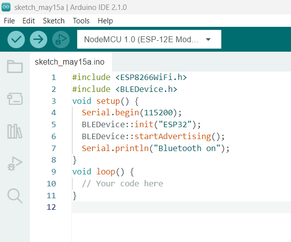
  #include <ESP8266WiFi.h>
  #include <BLEDevice.h>
  void setup() {
    Serial.begin(115200);
    BLEDevice::init("ESP32");
    BLEDevice::startAdvertising();
    Serial.println("Bluetooth on");
  }
  void loop() {
    // Your code here
  }
BLEDevice::init("ESP32") function initializes the Bluetooth subsystem with a custom name, and BLEDevice::startAdvertising() function starts advertising the device's presence to other Bluetooth devices.
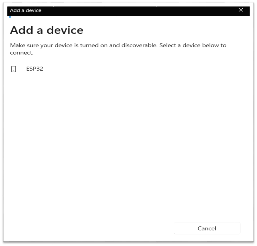
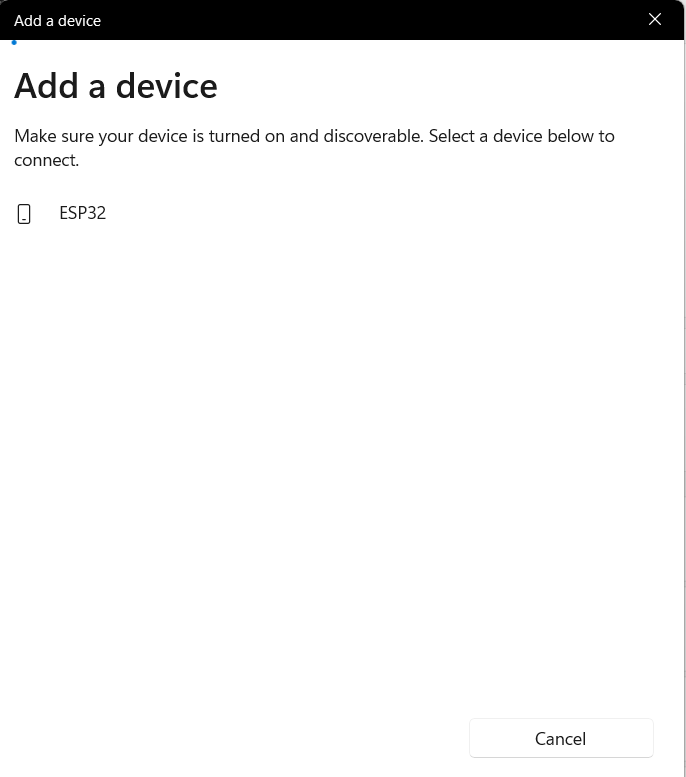
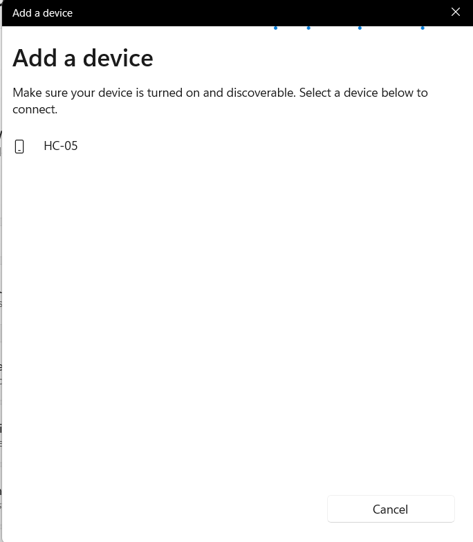
Once you upload this code to your ESP32 board and open the Bluetooth settings on a nearby device, you should see the ESP32 device listed as "ESP32" or whatever custom name you specified in the BLEDevice::init() function.
Note that in order to use the Bluetooth module on the ESP32, you need to have the necessary drivers and libraries installed in your development environment. You can download the ESP32 Arduino Core from the official website and install it using the Arduino IDE.
This code uses the Bluetooth Low Energy (BLE) module on the ESP32 to create a custom service with a characteristic that can be used to control an LED. When a client device connects to the ESP32, the LED starts blinking. The client device can then write a value of either 0 or 1 to the characteristic to turn the LED on or off.
The LEDCharacteristicCallback class defines the callback functions for the characteristic, including onWrite, which is called when a client writes to the characteristic, and onConnect and onDisconnect, which are called when a client connects or disconnects from the server.
To control the LED using Bluetooth, you can use a Bluetooth-enabled device, such as a smartphone or tablet, to connect to the ESP32 and write a value of either 0 or 1 to the characteristic. The ESP32 will then turn the LED on or off accordingly.
Controlling using external Bluetooth chip(same for ESP32 and ESP8266)
        #include <SoftwareSerial.h>
        SoftwareSerial BTserial(14, 12); // RX | TX
        const int ledPin = 2;
        void setup() {
          Serial.begin(115200);
          pinMode(ledPin, OUTPUT);
          BTserial.begin(9600);
          Serial.println("Bluetooth is Ready!");
        }
        void loop() {
          if (BTserial.available()) {
            char cmd = BTserial.read();
            if (cmd == '0') {
              digitalWrite(ledPin, LOW);
              Serial.println("LED OFF");
            } else if (cmd == '1') {
              digitalWrite(ledPin, HIGH);
              Serial.println("LED ON");
            }
          }
This code uses the SoftwareSerial library to create a serial port on pins 14 (RX) and 12 (TX) to communicate with the external Bluetooth chip. When the Bluetooth chip sends a value of either 0 or 1, the ESP32 will turn the LED on or off accordingly.
To use this code, you need to connect the external Bluetooth chip to the ESP using the RX and TX pins. You also need to pair the external Bluetooth chip with a Bluetooth-enabled device, such as a smartphone or tablet, and connect to the chip using a serial terminal app.
Once you're connected, you can send a value of either 0 or 1 to the chip to turn the LED on or off. The ESP will read the value from the serial port and turn the LED on or off accordingly.
Voice control via Bluetooth
We can give the voice command in esp using external Bluetooth module which convert text to string and send the string to esp board and control the system. This is also workable with Arduino board.
In this example we are controlling 3 LED light with voice.
I am using AMR voice app which is easy available on the internet. You can use any app you want.
A web server is a program that serves web pages and other content over the internet or an intranet. When you access a website, your web browser sends a request to the web server hosting that website, and the web server responds with the requested content, such as HTML files, images, videos, or other resources.
A web server runs on a computer or a server and listens for incoming requests on a specific port, usually port 80 for HTTP requests or port 443 for HTTPS requests. When a request comes in, the web server processes the request, retrieves the requested content from its file system or a database, and sends it back to the client that made the request. .
Web servers can be configured to support different protocols, such as HTTP, HTTPS, FTP, SMTP, or IMAP, and can also support different programming languages, frameworks, and libraries for building web applications. They can also handle different types of requests, such as static content requests or dynamic content requests that require server-side processing. .
Some popular web servers include Apache HTTP Server, Nginx, Microsoft IIS, and Google Web Server. In the context of IoT, microcontrollers and single-board computers like the ESP32 can also act as web servers to provide remote access to data and control of connected devices. .
Creating web server in esp32
    #include <WiFi.h>
    #include <WebServer.h>
    const char* ssid = "YOUR_SSID";
    const char* password = "YOUR_PASSWORD";
    WebServer server(80);
    void handleRoot() {
      server.send(200, "text/plain", "Hello from ESP32!");
    }
    void setup() {
      Serial.begin(115200);
      WiFi.begin(ssid, password);
      while (WiFi.status() != WL_CONNECTED) {
        delay(1000);
        Serial.println("Connecting to WiFi...");
      }
      Serial.println("Connected to WiFi");
      server.on("/", handleRoot);
      server.begin();
      Serial.println("Web server started");
    }
    void loop() {
      server.handleClient();
    }
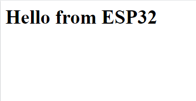
This code creates a web server on port 80 using the WebServer library. When a client connects to the server and requests the root path ("/"), the server will send a "Hello from ESP32!" message back to the client.
To use this code, you need to connect the ESP32 to your Wi-Fi network by setting the ssid and password variables to your Wi-Fi network name and password, respectively. Once the ESP32 is connected to Wi-Fi, you can open a web browser and navigate to the IP address of your ESP32 to see the "Hello from ESP32!" message.
Note that this is a very simple example and the WebServer library can be used to create more complex web servers with multiple routes and dynamic content.
Creating web server in esp8266
        #include <ESP8266WiFi.h>
        #include <ESP8266WebServer.h>

        const char* ssid = "YOUR_SSID";
        const char* password = "YOUR_PASSWORD";
        ESP8266WebServer server(80);
        void handleRoot() {
          server.send(200, "text/plain", "Hello from ESP8266!");
        }
        void setup() {
          Serial.begin(115200);
          WiFi.begin(ssid, password);
          while (WiFi.status() != WL_CONNECTED) {
            delay(1000);
            Serial.println("Connecting to WiFi...");
          }
          Serial.println("Connected to WiFi");
          server.on("/", handleRoot);
          server.begin();
          Serial.println("Web server started");
        }
        void loop() {
          server.handleClient();
        }
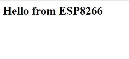
This code creates a web server on port 80 using the ESP8266WebServer library. When a client connects to the server and requests the root path ("/"), the server will send a "Hello from ESP8266!" message back to the client.
To use this code, you need to connect the ESP8266 to your Wi-Fi network by setting the ssid and password variables to your Wi-Fi network name and password, respectively. Once the ESP8266 is connected to Wi-Fi, you can open a web browser and navigate to the IP address of your ESP8266 to see the "Hello from ESP8266!" message.
Note that this is a very simple example and the ESP8266WebServer library can be used to create more complex web servers with multiple routes and dynamic content.
Pulse Wave Modulation
Pulse Width Modulation (PWM) is a common technique used in electronics to control the amount of power delivered to a load, such as an LED, motor, or heater. It works by rapidly turning a voltage source on and off at a specific frequency, and varying the width of the on-time or duty cycle of the pulse wave. This allows us to effectively adjust the amount of power that the load receives without changing the voltage level.
In Microcontroller, PWM is commonly used to control the brightness of an LED, the speed of a motor, or the temperature of a heater. The Arduino has built-in hardware support for PWM on certain pins, allowing us to easily generate pulse waves of varying duty cycles.
To use PWM in Microcontroller, we can use the analogWrite() function, which sends a PWM signal to a specific pin. The analogWrite() function takes two arguments: the first is the pin number, and the second is the duty cycle, which can range from 0 (always off) to 255 (always on). .
NOTE: PWM is also supported in Arduino boards
    const int ledPin = D2; // the pin number of the LED
    int brightness = 0; // initial LED brightness
    int fadeAmount = 5; // amount to fade the LED by
    void setup() {
      pinMode(ledPin, OUTPUT); // set the LED pin as an output
    }
    void loop() {
      analogWrite(ledPin, brightness); // set the LED brightness using PWM
      brightness += fadeAmount; // increase or decrease the LED brightness
      if (brightness <= 0 || brightness >= 255) { // if brightness is at min or max
        fadeAmount = -fadeAmount; // reverse the fade direction
      }
      delay(30); // wait for a short period before updating the brightness again
    }
This code sets up an LED on pin 9 and uses the analogWrite() function to set the LED brightness using PWM. The LED brightness is increased or decreased by a fixed amount (fadeAmount) each time the loop() function is called, and the direction of the fade is reversed when the brightness reaches the minimum or maximum level.
To use this code, connect an LED to pin 9 of your Arduino board (with a current-limiting resistor if necessary), upload the code to the board, and watch as the LED fades in and out smoothly. You can adjust the fadeAmount variable to change the speed of the fade, and the delay() function to change the delay between brightness updates.
Note that PWM can also be used to control the speed of a motor, the temperature of a heater, or the intensity of a speaker, among other things. The analogWrite() function can be used to set the PWM output on any pin that supports PWM, which can vary depending on the specific Arduino board you are using. Check your board's documentation to see which pins support PWM.
Getting updates via OTA
OTA (Over-The-Air) update allows you to upload new firmware to your ESP32 or ESP8266 board wirelessly, without the need to physically connect it to your computer with a USB cable.