Sensors are devices that detect and respond to changes in the physical environment. They convert physical quantities such as temperature, light, sound, pressure, and humidity into electrical signals that can be read and processed by a computer or microcontroller.
Sensors can be classified into several categories based on the physical quantities they measure, such as:
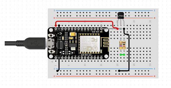
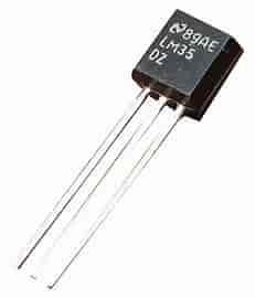
Temperature sensors: These sensors measure the temperature of a system or environment. Examples include thermocouples, thermistors, and temperature-sensitive resistors.
Pressure sensors: These sensors measure the pressure of a fluid or gas. Examples include piezoelectric sensors, capacitive sensors, and strain gauges.
Humidity sensors: These sensors measure the amount of water vapor in the air or other gases. Examples include capacitive sensors, resistive sensors, and thermal conductivity sensors.
Light sensors: These sensors measure the intensity or brightness of light. Examples include photodiodes, phototransistors, and photoresistors.
Motion sensors: These sensors detect motion or movement in a system or environment. Examples include accelerometers, gyroscopes, and magnetometers.
Chemical sensors: These sensors detect the presence of specific chemicals or gases. Examples include gas sensors, pH sensors, and biosensors.
Sensors play a critical role in a wide range of applications, including environmental monitoring, industrial control, medical devices, and consumer electronics. With the increasing prevalence of the Internet of Things (IoT), sensors are becoming more ubiquitous and are being used to gather data in real-time to enable smarter decision-making.
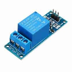
A relay is an electrical device that is used to control the flow of electricity in a circuit. It is an electromagnetic switch that can be used to turn on or off a circuit. The main purpose of a relay is to isolate a low voltage circuit from a high voltage circuit. It allows a low power signal to control a high power load.
A relay consists of two circuits, a control circuit and a load circuit. The control circuit is usually a low voltage circuit that is connected to a sensor or a microcontroller. The load circuit is a high voltage circuit that is connected to the electrical device that needs to be controlled.
The control circuit consists of an electromagnet, which when energized, creates a magnetic field that pulls a metal armature towards it. This metal armature is connected to a set of contacts that can either open or close a circuit. When the electromagnet is not energized, the contacts are in their normal state, and the circuit is open. When the electromagnet is energized, the contacts are pulled towards it, and the circuit is closed.
Relays are available in different types, and they are chosen based on the type of load that needs to be controlled. Some common types of relays include:
Electromechanical Relays: These are the most common type of relays. They are used for switching low to medium voltage loads.
Solid State Relays: These are electronic devices that use semiconductor switches instead of mechanical contacts. They are used for switching low to medium voltage loads.
Reed Relays: These relays use a magnetic field to open and close contacts. They are used for switching low voltage loads.
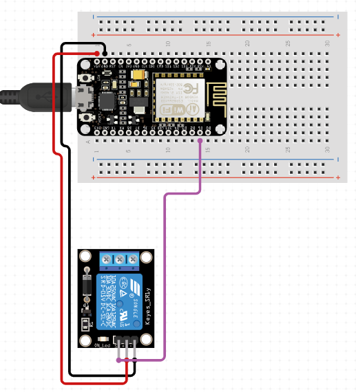
Controlling relay using ESP32
#include <ESPAsyncWebServer.h>
const int relayPin = D1; // GPIO4 pin
AsyncWebServer server(80);
void setup() {
pinMode(relayPin, OUTPUT); // set the GPIO pin to output mode
server.on("/", HTTP_GET, [](AsyncWebServerRequest *request){
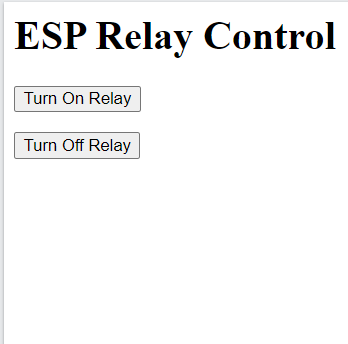
String html = "<html><head><title>ESP Relay Control</title></head>";
html += "<body><h1>ESP Relay Control</h1>";
html += "<form action=\"/on\" method=\"get\"><button>Turn On Relay</button></form>";
html += "<form action=\"/off\" method=\"get\"><button>Turn Off Relay</button></form>";
html += "</body></html>";
request->send(200, "text/html", html);
});
server.on("/on", HTTP_GET, [](AsyncWebServerRequest *request){
digitalWrite(relayPin, HIGH); // turn on the relay
request->send(200, "text/plain", "Relay turned on");
});
server.on("/off", HTTP_GET, [](AsyncWebServerRequest *request){
digitalWrite(relayPin, LOW); // turn off the relay
request->send(200, "text/plain", "Relay turned off");
});
server.begin();
}
void loop() {
// put your main code here, to run repeatedly
}
NOTE: You can also use ESP8266/bluetooth to control the relay
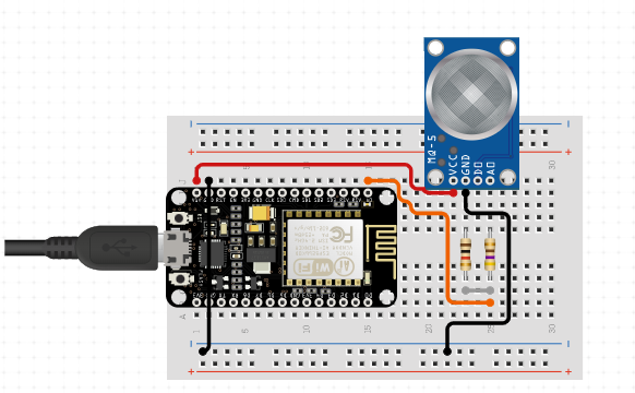
Gas sensor module
Gas sensors are electronic devices that detect and measure different types of gases in the air. They are commonly used in industrial, commercial, and residential settings to ensure safe working conditions and prevent potential health hazards.
There are different types of gas sensors that can detect specific gases such as carbon monoxide, methane, propane, and hydrogen sulfide. Some gas sensors are also capable of detecting multiple gases simultaneously.
The functioning of gas sensors depends on their type and technology used, but they generally work by detecting the changes in the electrical conductivity of a material or changes in the absorption of light in a specific wavelength range. These changes are caused by the presence of gases in the air, which can then be detected and measured by the sensor.
Gas sensors are used in a wide range of applications, including in gas detectors, air quality monitors, gas leak detectors, and automotive emissions control systems. They are also used in smart homes to monitor the indoor air quality and to automatically adjust the ventilation system.
Types of sensors
MQ-2 - Methane, Butane, LPG, smoke
MQ-3 - Alcohol, Ethanol, smoke
MQ-4 - Methane, CNG Gas
MQ-5 - Natural gas, LPG
MQ-6 - LPG, butane gas
MQ-7 - Carbon Monoxide
MQ-8 - Hydrogen Gas
MQ-9 - Carbon Monoxide, flammable gasses
MQ131 - Ozone
MQ135 - Air Quality (CO, Ammonia, Benzene, Alcohol, smoke)
Controlling gas sensor with Arduino
    int CO_PIN = A0;
    void setup() {
      Serial.begin(9600);
    }
    void loop() {
      float sensor_voltage = analogRead(CO_PIN) * (5.0 / 1023.0);  // convert analog value to voltage
      float co_concentration = 200.0 * sensor_voltage;  // convert voltage to CO concentration (ppm)
      Serial.print("CO Concentration: ");
      Serial.print(co_concentration);
      Serial.println(" ppm");
      delay(1000);
    }
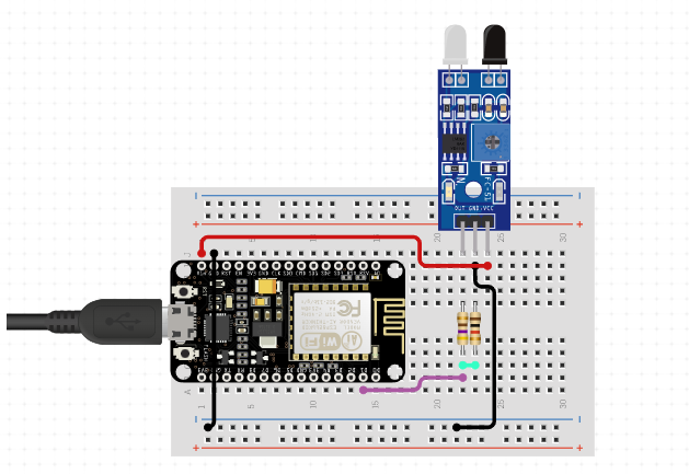
IR Sensor
An IR (Infrared) sensor is an electronic component that detects IR radiation in its surrounding environment and converts it into an electrical signal. It works on the principle of emitting IR rays and then detecting the reflection of those rays from a nearby object.
IR sensors are widely used in various applications, such as robotics, automation, and security systems. In Arduino projects, IR sensors are often used for obstacle detection, line following, and object tracking.
To use an IR sensor with an Arduino board, you first need to connect it to the board using wires. Most IR sensors have three pins - Vcc, GND, and Signal. Vcc and GND are connected to the 5V and GND pins of the Arduino board, respectively. The Signal pin is connected to any digital pin of the board.
Getting data of IR sensor in Arduino
    int irPin = D1; // IR sensor connected to pin 2
    int irValue = 0; // variable to store the sensor reading
    void setup() {
      Serial.begin(9600); // initialize serial communication at 9600 bits per second
    }
    void loop() {
      irValue = analogRead(irPin); // read the analog value from the IR sensor
      Serial.println(irValue); // print the sensor reading to the serial monitor
      delay(1000); // wait for 1 second before reading again
    }
In this code, the analogRead() function is used to read the analog value of the IR sensor connected to pin 2. The value is then printed to the serial monitor using the Serial.println() function. The delay() function is used to pause the program for 1 second before reading again.
Note that the actual analog value received from the sensor will depend on various factors, such as the distance between the sensor and the object, the reflectivity of the object, and the ambient light conditions. You may need to calibrate the sensor and adjust the threshold values in your code accordingly to get the desired results.
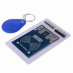
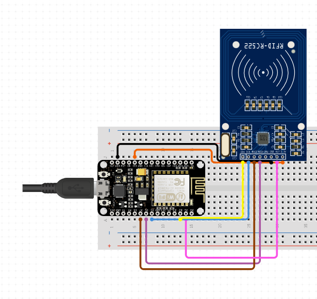
RFID Sensor
RFID stands for Radio Frequency Identification, and it is a technology used to identify and track objects using radio waves. It consists of two main components: an RFID tag and an RFID reader.
The RFID tag, which is also known as a transponder or a smart label, contains a microchip and an antenna. The microchip stores the unique identification number of the object or person being tracked, while the antenna transmits this information to an RFID reader when it is within range.
The RFID reader, also known as an interrogator, emits a radio signal that activates the RFID tag and reads the data stored on the microchip. The reader then processes the data and sends it to a computer or other device for further processing.
RFID technology is used in a variety of applications, such as inventory management, supply chain management, access control, and security. It is also used in contactless payment systems, such as credit cards and mobile payment apps.
In summary, RFID technology allows for the identification and tracking of objects and people using radio waves, and it has numerous practical applications in various industries.
    #include <SPI.h>
    #include <MFRC522.h>
    #define SS_PIN D2
    #define RST_PIN D1
    MFRC522 rfid(SS_PIN, RST_PIN);
    void setup() {
      Serial.begin(9600); // Initialize serial communication
      SPI.begin(); // Initialize SPI bus
      rfid.PCD_Init(); // Initialize MFRC522 RFID reader
      Serial.println("Ready to scan RFID tag");
    }
    void loop() {
      // Look for new cards
      if (rfid.PICC_IsNewCardPresent() && rfid.PICC_ReadCardSerial()) {
        // Show card UID on serial monitor
        Serial.print("Card UID: ");
        for (byte i = 0; i < rfid.uid.size; i++) {
          Serial.print(rfid.uid.uidByte[i] < 0x10 ? "0" : "");
          Serial.print(rfid.uid.uidByte[i], HEX);
        }
        Serial.println();
      }
      rfid.PICC_HaltA(); // Stop reading RFID tag
      rfid.PCD_StopCrypto1(); // Stop encryption on PCD
      delay(1000); // Wait for 1 second before scanning for a new tag
    }
This code initializes the SPI bus and the RFID sensor using the MFRC522 library. It then waits for a new card to be present and reads its UID (unique identifier) using the rfid.PICC_ReadCardSerial() function. The UID is then printed on the serial monitor using the Serial.print() function. Finally, the code waits for 1 second before scanning for a new card.
Health sensor
Health sensors in Arduino are electronic devices that can be used to monitor various aspects of a person's health, including heart rate, blood pressure, body temperature, and more. These sensors are often used in wearable health devices that can track and analyze an individual's health data over time.
Heart rate sensors:These sensors use infrared or optical technology to measure a person's heart rate and can be worn on the wrist or chest.
Blood pressure sensors: These sensors measure blood pressure using a cuff that is placed around the arm.
Body temperature sensors: These sensors can be used to measure a person's body temperature using either a thermistor or infrared technology.
Electrocardiogram (ECG) sensors: These sensors measure the electrical activity of the heart and can be used to detect irregular heart rhythms.
Pulse oximeters: These sensors measure the amount of oxygen in a person's blood and can be worn on the fingertip.
To use these sensors with Arduino, you will need to connect the sensor to the appropriate pins on the Arduino board and write code to read and interpret the sensor data. There are many tutorials and example code available online that can help you get started with using health sensors with Arduino.
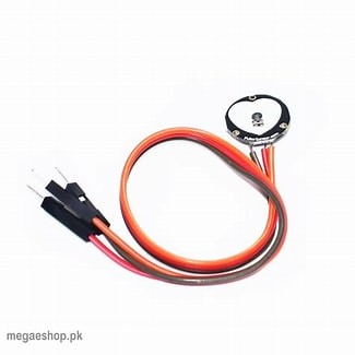
Heart Rate Sensor
A heart rate sensor is a sensor that measures a person's heart rate or pulse. In Arduino, we can use various heart rate sensors to measure the heart rate of a person and use the data for different applications.
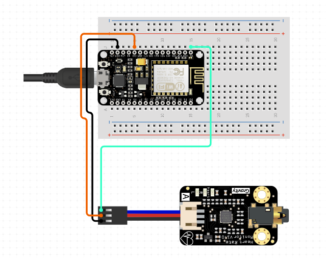
One commonly used heart rate sensor is the Pulse Sensor. The Pulse Sensor is a small, low-cost sensor that can be used to measure a person's heart rate and is compatible with Arduino. The sensor works by detecting changes in blood volume in the fingertip as the heart beats.
To use the Pulse Sensor with Arduino, we need to connect the sensor to the Arduino board and write a code to read the sensor data and display the heart rate.
    // Pulse Sensor Arduino Sketch
    #include <PulseSensor.h>
    // Attach PulseSensor's SIG pin to analog pin A0
    const int pulseSensorPin = A0;
    // Variables
    int pulseSensorValue;
    int heartRate;
    PulseSensor pulseSensor;
    void setup() {
      Serial.begin(9600);
      pulseSensor.begin(pulseSensorPin);
    }
    void loop() {
      pulseSensorValue = pulseSensor.getSignal();
      if (pulseSensorValue > 0) {
        heartRate = pulseSensor.getBeatsPerMinute();
        Serial.print("Heart Rate: ");
        Serial.println(heartRate);
      }
    }
In this code, we first include the PulseSensor library and declare the sensor's SIG pin as an analog input. We also declare variables to store the sensor data and heart rate.
In the setup function, we begin the serial communication and initialize the PulseSensor object.
In the loop function, we read the sensor data and check if the data is valid. If the data is valid, we calculate the heart rate using the getBeatsPerMinute function and display it on the Serial Monitor using the Serial.print and Serial.println functions.
Blood pressure sensor
A blood pressure sensor is a device that measures the force of blood against the walls of arteries as the heart pumps blood through the body. Blood pressure is typically measured using an inflatable cuff that is placed around the upper arm, and the pressure is measured using a manometer. However, newer blood pressure sensors use electronic or optical techniques to measure blood pressure non-invasively. These sensors are often used in medical settings to monitor patients with hypertension or other cardiovascular conditions, but they can also be used in wearable devices for personal health monitoring.
      // Define analog pin for sensor data
      #define PRESSURE_PIN A0
      // Variables to store raw and calculated values
      int rawPressure;
      float kPaPressure;
      void setup() {
        Serial.begin(9600);
      }
      void loop() {
        // Read raw sensor value
        rawPressure = analogRead(PRESSURE_PIN);
        // c (kPa): ");
        Serial.println(kPaPressure);
        delay(1000);
      }
Body temperature sensor
Body temperature sensors are electronic devices that measure the temperature of the human body. These sensors can be used to monitor the temperature of a person and are commonly used in healthcare settings. Body temperature sensors come in various forms, including infrared sensors and thermistors.
Infrared sensors are non-contact sensors that detect the infrared radiation emitted by the human body. These sensors can be used to measure the temperature of the skin or the ear canal. Thermistors, on the other hand, are contact sensors that measure the temperature of the body by coming into contact with the skin.
Arduino is a popular platform for building body temperature sensors. The sensors can be connected to the Arduino board and programmed to display the temperature on an LCD screen or send the data to a computer for analysis.
In this code, the Adafruit_MLX90614 library is used to interface with the infrared temperature sensor. The mlx.readObjectTempC() function is used to read the temperature from the sensor, and the temperature is printed to the serial monitor using the Serial.print() function.
Electrocardiogram (ECG) sensors
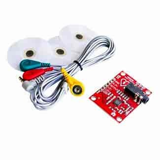
ECG (Electrocardiogram) sensor is a medical device that detects the electrical activity of the heart over a period of time. ECG sensors are used to monitor and diagnose heart conditions such as arrhythmias, heart attacks, and other heart-related problems.
To use ECG sensor with Arduino, we need an ECG sensor module such as the AD8232 module. The module has three electrodes, which should be placed on the chest of the patient to obtain the ECG signal. The ECG signal is then amplified and processed by the module, which produces a voltage output that can be read by an Arduino.
      #include <SoftwareSerial.h>
      int outputPin = 10;          // Output pin for the LED
      int x;                       // Variable to store ECG data
      void setup() {
        Serial.begin(9600);        // Initialize serial communication
        pinMode(outputPin, OUTPUT);// Initialize LED pin as an output
      }
      void loop() {
        x = analogRead(A0);        // Read ECG data from analog input A0
        Serial.println(x);         // Send ECG data to the serial monitor
        if (x > 600) {             // If ECG data is above a certain threshold
          digitalWrite(outputPin, HIGH);  // Turn on LED
        } else {
          digitalWrite(outputPin, LOW);   // Turn off LED
        }
        delay(10);                 // Delay to allow time for next ECG reading
      }
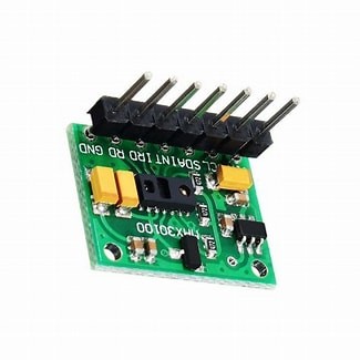
Pulse oximeter
Pulse oximeter is a non-invasive medical device used to measure oxygen saturation level and pulse rate in the blood. It is often used in hospitals and healthcare settings, but it can also be used at home to monitor one's health. The pulse oximeter works by shining a light through a person's finger or earlobe, and then measuring the amount of light that passes through the blood vessels. Based on the amount of light that passes through, the device can determine the oxygen saturation level and pulse rate.
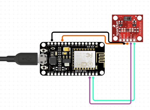
To use a pulse oximeter with Arduino, you will need a compatible sensor module, such as the MAX30100 or MAX30102. These modules contain an integrated photodetector and LED to measure blood oxygen saturation levels. The module communicates with the Arduino through the I2C interface.
        #include <Wire.h>
        #include "MAX30105.h"
        #include "heartRate.h"

        MAX30105 particleSensor;
        const byte RATE_SIZE = 4; // Increase this for more averaging. 4 is good.
        byte rates[RATE_SIZE]; // Array of heart rates
        byte rateSpot = 0;
        long lastBeat = 0; // Time at which the last beat occurred
        float beatsPerMinute;
        int beatAvg;
        void setup() {
          Serial.begin(115200);
          Serial.println("Initializing...");
          particleSensor.begin(Wire, I2C_SPEED_FAST);
          particleSensor.setup(); // Configure sensor with default settings
          particleSensor.setPulseAmplitudeRed(0x0A);
          particleSensor.setPulseAmplitudeGreen(0);
        }
        void loop() {
          long irValue = particleSensor.getIR();
          if (checkForBeat(irValue) == true) {
            // We sensed a beat!
            long delta = millis() - lastBeat;
            lastBeat = millis();
            beatsPerMinute = 60 / (delta / 1000.0);
            if (beatsPerMinute < 255 && beatsPerMinute > 20) {
              rates[rateSpot++] = (byte)beatsPerMinute; // Store this reading in the array
              rateSpot %= RATE_SIZE; // Wrap variable

              // Take average of readings
              beatAvg = 0;
              for (byte x = 0 ; x < RATE_SIZE ; x++)
                beatAvg += rates[x];
              beatAvg /= RATE_SIZE;
            }
          }
          Serial.print("Heart rate: ");
          Serial.print(beatAvg);
          Serial.println(" bpm");
        }
This code uses the MAX30105 library to communicate with the sensor module and retrieve the heart rate data. It also uses the heartRate library to detect heart rate from the sensor readings. The heart rate readings are stored in an array for averaging, and the final heart rate value is printed to the serial monitor.
Potentiometer
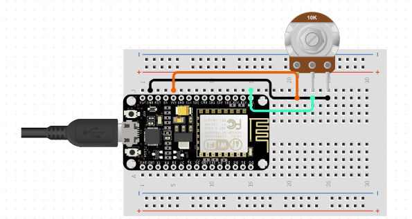
A potentiometer is a type of variable resistor that has three terminals - one connected to the wiper, which moves along a resistive element as the potentiometer knob is turned, and two others connected to the ends of the resistive element. The potentiometer is used to control the voltage or resistance in a circuit, making it a popular component in a wide range of electronic devices.
In Arduino, the potentiometer can be used to control the brightness of an LED, the speed of a motor, or any other variable that can be controlled by changing the resistance or voltage in a circuit. The potentiometer can be connected to an analog input pin on the Arduino board, which measures the voltage at the wiper terminal and converts it to a digital value using an analog-to-digital converter (ADC). The ADC produces a 10-bit value, which can be used to control the output of the circuit.
int potPin = A0;    // analog input pin for the potentiometer
int ledPin = 9;     // digital output pin for the LED
int brightness;     // variable to store the LED brightness value
void setup() {
  pinMode(ledPin, OUTPUT);   // set the LED pin as an output
}
void loop() {
  brightness = analogRead(potPin);   // read the potentiometer value
  brightness = map(brightness, 0, 1023, 0, 255);   // map the value to 0-255 range
  analogWrite(ledPin, brightness);   // set the LED brightness
}
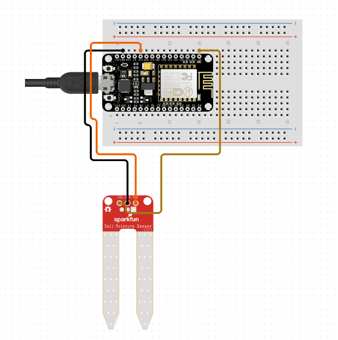
Soil moisture sensor
Soil moisture sensors are electronic devices used to measure the amount of water present in the soil. These sensors are commonly used in agriculture and gardening applications to optimize irrigation and prevent over-watering or under-watering of crops. Soil moisture sensors can be either analog or digital and use different methods to measure the amount of moisture in the soil.
Analog soil moisture sensors work on the principle of varying resistance. As the soil moisture level changes, the resistance of the sensor changes, which can be measured by the microcontroller or Arduino board connected to the sensor. Digital soil moisture sensors work by using a capacitance-based method. They measure the amount of water in the soil by measuring the dielectric constant of the soil, which changes as the moisture level changes.
To use a soil moisture sensor with Arduino, you first need to connect it to the board. Analog sensors typically have two output pins, one connected to the analog input of the Arduino board, and the other connected to the ground pin. Digital sensors have three pins, power, ground, and signal. Once connected, you can use the analogRead() function in the Arduino IDE to read the analog values from the sensor, or you can use the digitalRead() function for digital sensors.
    int soilMoisturePin = A0; // analog input pin for soil moisture sensor
    int soilMoistureValue = 0; // variable to store soil moisture value
    void setup() {
      Serial.begin(9600); // initialize serial communication
    }
    void loop() {
      soilMoistureValue = analogRead(soilMoisturePin); // read soil moisture value
      Serial.print("Soil Moisture: "); // print output
      Serial.println(soilMoistureValue);
      delay(1000); // delay for 1 second
    }
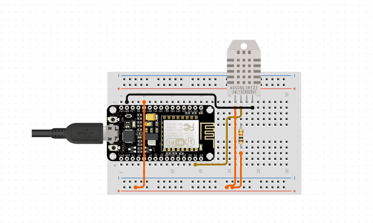
DHT sensor
DHT sensors are a type of sensor used to measure temperature and humidity in the surrounding environment. These sensors are widely used in various applications including weather monitoring, agriculture, indoor climate control, and more.
The term DHT refers to a family of sensors developed by Adafruit Industries, which includes the DHT11, DHT21, and DHT22 sensors. These sensors work by measuring the change in resistance of a humidity-sensitive element as the relative humidity changes in the surrounding envronment. This resistance value is then used to calculate the humidity of the air.
In addition to measuring humidity, the DHT sensors also have a built-in temperature sensor. The DHT11 is a basic, low-cost sensor that has an accuracy of ±2°C for temperature and ±5% for relative humidity. The DHT21 and DHT22 are more advanced and accurate sensors, with an accuracy of ±0.5°C for temperature and ±2% for relative humidity.
To use a DHT sensor with an Arduino, you will need to connect it to the appropriate pins on the Arduino board and install the appropriate libraries. The libraries allow you to easily read the values from the sensor and use them in your Arduino code.
    #include <DHT.h>
    #define DHTPIN 2     // Digital pin connected to the DHT sensor
    #define DHTTYPE DHT11   // DHT 11
    DHT dht(DHTPIN, DHTTYPE);
    void setup() {
      Serial.begin(9600);
      dht.begin();
    }
    void loop() {
      delay(2000);
      float h = dht.readHumidity();
      float t = dht.readTemperature();
      Serial.print("Humidity: ");
      Serial.print(h);
      Serial.print("%  Temperature: ");
      Serial.print(t);
      Serial.println("°C ");
    }
In this code, the DHT sensor is connected to digital pin 2 on the Arduino board. The DHT11 type is used, and the DHT library is included at the beginning of the code. The setup() function initializes the serial communication and the DHT sensor. The loop() function reads the humidity and temperature values from the sensor and prints them to the serial monitor every 2 seconds.
GPS sensor
A GPS (Global Positioning System) sensor is a device that is used to determine the precise geographical location of an object or person using GPS satellites. GPS sensors can be interfaced with microcontrollers like Arduino to extract location data and use it for various applications.
To use a GPS sensor with an Arduino, the sensor is typically connected to the Arduino's serial communication pins (Tx and Rx). The sensor communicates with the Arduino using a standardized communication protocol called NMEA (National Marine Electronics Association) 0183, which provides information about the GPS data.
The GPS sensor can be used to extract various types of location data such as latitude, longitude, altitude, and time. The extracted data can be used to create maps, track the movement of objects, and even determine the speed and direction of movement.
To read the GPS data in Arduino, we can use the SoftwareSerial library to establish a serial communication between the GPS sensor and the Arduino. The TinyGPS library can be used to decode the NMEA data and extract the required information.
    #include <SoftwareSerial.h>
    #include <TinyGPS.h>
    // Define the RX and TX pins for the GPS module
    SoftwareSerial gpsSerial(3, 4);
    // Define the TinyGPS object
    TinyGPS gps;
    void setup()
    {
      Serial.begin(9600);
      gpsSerial.begin(9600);
    }
    void loop()
    {
      // Check if there is GPS data available
      while (gpsSerial.available() > 0)
      {
        // Read the GPS data
        char c = gpsSerial.read();
        gps.encode(c);
      }
        // Extract the GPS data
      float latitude, longitude;
      unsigned long fix_age, time, date;
      int year;
      byte month, day, hour, minute, second, hundredths;
      gps.f_get_position(&latitude, &longitude, &fix_age);
      gps.crack_datetime(&year, &month, &day, &hour, &minute, &second, &hundredths);
        // Print the GPS data
      Serial.print("Latitude: ");
      Serial.println(latitude, 6);
      Serial.print("Longitude: ");
      Serial.println(longitude, 6);
      Serial.print("Date/Time: ");
      Serial.print(month);
      Serial.print("/");
      Serial.print(day);
      Serial.print("/");
      Serial.print(year);
      Serial.print(" ");
      Serial.print(hour);
      Serial.print(":");
      Serial.print(minute);
      Serial.print(":");
      Serial.println(second);
          // Wait for a few seconds
      delay(5000);
    }
Vibration sensor
A vibration sensor, also known as a piezoelectric sensor, is an electronic device that measures and detects vibrations or shocks in a system. It converts mechanical vibrations into electrical signals that can be read by a microcontroller, such as an Arduino board.
The basic working principle of a vibration sensor is based on the piezoelectric effect, where certain materials produce an electric charge when they are subjected to mechanical stress or deformation. The piezoelectric material in the sensor produces an electric charge when it is subjected to vibrations or shockwaves. This electric charge is then amplified and processed by the circuitry in the sensor to produce an output signal that is proportional to the intensity of the vibration or shock.
Vibration sensors can be used in a variety of applications, such as structural health monitoring, machine condition monitoring, and vibration analysis. In Arduino projects, vibration sensors are commonly used to detect the presence or absence of vibrations in a system, such as an earthquake, or to monitor the vibration levels of a motor or other machinery.
    int sensorPin = A0; // connect the output of vibration sensor to analog pin A0
    int threshold = 100; // adjust this value to set the sensitivity of the sensor
    void setup() {
      Serial.begin(9600); // initialize serial communication
    }
    void loop() {
      int sensorValue = analogRead(sensorPin); // read the sensor value
      Serial.print("Sensor value: ");
      Serial.println(sensorValue);
      if (sensorValue > threshold) { // check if the sensor value is greater than the threshold
        Serial.println("Vibration detected!"); // print a message to serial monitor
        // do something when vibration is detected, such as turning on an LED
      }
      delay(100); // wait for a short time before taking another sensor reading
    };
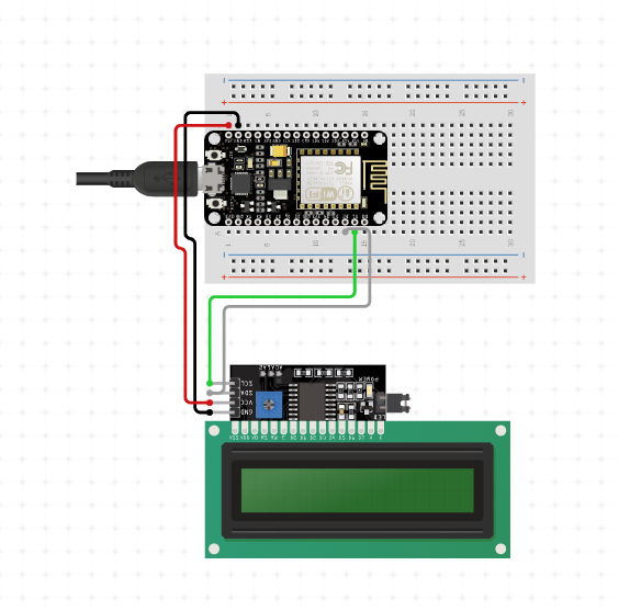
Display
In Arduino, display refers to the output device used to display information or data from the microcontroller. There are many types of displays available for use with Arduino, including LCD displays, LED displays, OLED displays, and TFT displays.
LCD displays, or Liquid Crystal Displays, are one of the most commonly used display types for Arduino projects. They are available in various sizes and can display alphanumeric characters, as well as simple graphics. LCD displays typically have a backlight that can be turned on or off as needed.
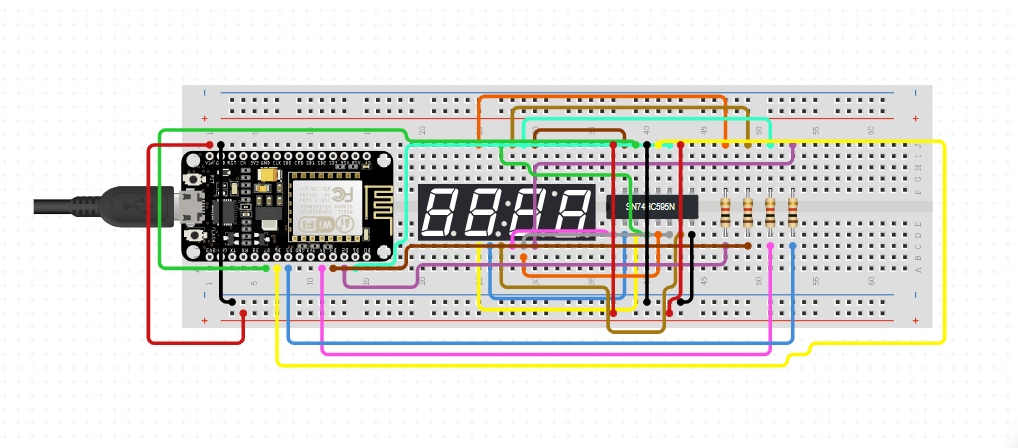
LED displays are another popular type of display for Arduino projects. They are used to display simple numeric or alphanumeric data and are available in different colors, such as red, green, and blue. LED displays are often used in applications where high visibility is required, such as in digital clocks, temperature displays, and scoreboards.
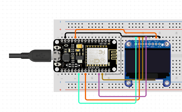
OLED displays, or Organic Light Emitting Diode displays, are a newer type of display that offer high contrast and high resolution. They are available in various sizes and can display both text and graphics. OLED displays are often used in wearable devices, such as smartwatches, due to their low power consumption.
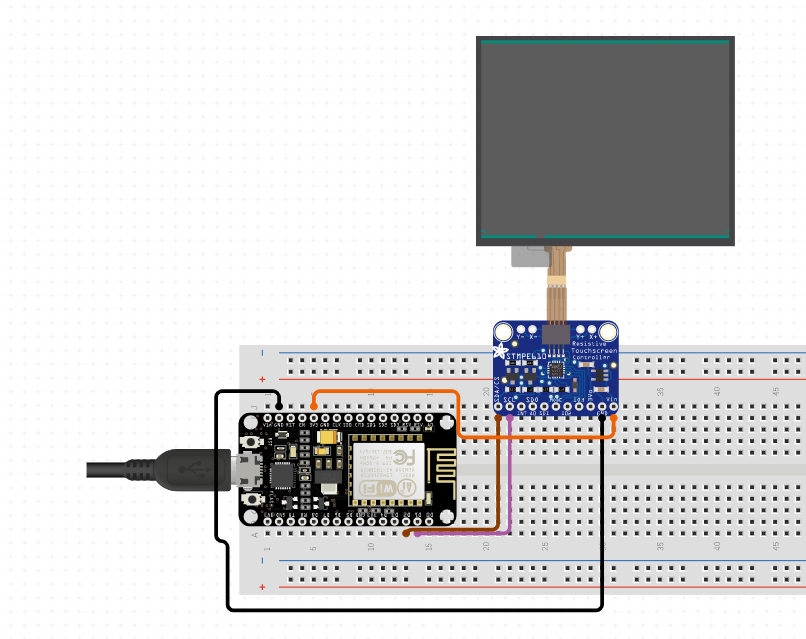
TFT displays, or Thin Film Transistor displays, are high-resolution displays that can display both text and graphics in full color. They are available in various sizes and can be used in a variety of applications, such as GPS navigation systems, gaming devices, and digital cameras.
In Arduino, displays can be connected to the microcontroller using different types of communication protocols, such as I2C, SPI, and parallel. The specific protocol used will depend on the type of display being used and its communication requirements.
To display information on a display in an Arduino project, the appropriate library for the display type must be included in the sketch, and the necessary commands must be written to control the display. For example, to display text on an LCD display, the LiquidCrystal library can be used, while for OLED displays, the Adafruit_SSD1306 library can be used.
There are several types of displays that are compatible with Arduino boards, some of the most common ones are:
LCD (Liquid Crystal Display): LCD displays are popular for their low power consumption and simple interface. They can display alphanumeric characters, and some models have the ability to display graphics. There are different types of LCD displays, including 16x2, 20x4, etc.
OLED (Organic Light Emitting Diode) Display: OLED displays have a higher resolution and contrast than LCD displays and have thLEe ability to display graphics and text. They also consume less power and have a faster response time. OLED displays are available in different sizes and colors.
LED (Light Emitting Diode) Display: LED displays are commonly used for displaying simple information such as temperature, time, and voltage. They come in different sizes and colors, and can be either 7-segment or dot matrix.
TFT (Thin Film Transistor) Display: TFT displays are high-quality displays that offer high resolution, fast response time, and excellent color reproduction. They can be used to display graphics, images, and videos. TFT displays are available in different sizes and interfaces, such as SPI and I2C.
E-Paper Display: E-paper displays are low power displays that can retain an image even when power is turned off. They are commonly used in e-readers and other applications where power consumption is a concern. E-paper displays are available in different sizes and interfaces.
LCD display with microcontroller
        #include <LiquidCrystal.h>
        // Initialize the library with the numbers of the interface pins
        LiquidCrystal lcd(12, 11, 5, 4, 3, 2);
        void setup() {
          // Set up the LCD's number of columns and rows
          lcd.begin(16, 2);
          // Print a message to the LCD
          lcd.print("Hello, world!");
        }
        void loop() {
          // Do nothing
        }
Motors are widely used with Arduino boards to control the movement of robots, vehicles, and other mechanical devices. There are different types of motors that can be used with Arduino, such as DC motors, servo motors, and stepper motors.
DC Motors:
DC motors are the simplest type of motors and they work based on the principle of electromagnetism. They are used to convert electrical energy into mechanical energy. DC motors have a rotating armature and a stationary field. The direction of rotation of the motor can be changed by reversing the polarity of the voltage applied to the motor. DC motors can be controlled using a motor driver circuit that interfaces between the Arduino board and the motor.
Servo Motors:
Servo motors are commonly used in robotics and other applications where precise control of the motor position is required. Servo motors have a built-in feedback mechanism that allows the controller to precisely control the motor's position. They are typically used for controlling the movement of robot arms and legs, as well as for steering remote control cars and planes.
Stepper Motors:
Stepper motors are commonly used in CNC machines, 3D printers, and other applications where precise control of the motor position is required. Stepper motors can be controlled using the Arduino board by sending a sequence of electrical pulses to the motor's coils. Each pulse causes the motor to move a precise amount, which allows for accurate control of the motor's position.
BLDC motor
BLDC stands for Brushless DC motors. These are electric motors that are designed to operate using electronic commutation instead of brushes. The electronic commutation replaces the traditional commutation, which is done using brushes, with a-+n electronic circuit that switches the current flow to the motor windings based on the rotor position.
Using a dc motor with Arduino
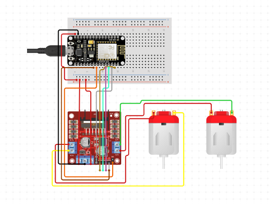
Using a DC motor with Arduino requires connecting the motor to a motor driver module that controls the motor's direction and speed. Here are the steps to use a DC motor with Arduino:
Gather the materials - You will need an Arduino board, a DC motor, a motor driver module, a breadboard, and jumper wires.
Connect the motor driver module to the breadboard, and connect VCC and GND pins of the module to the 5V and GND pins of the Arduino board, respectively.
Connect the motor to the motor driver module - Connect the motor's positive terminal to the OUT1 pin of the module and the negative terminal to the OUT2 pin.
Connect the control pins of the motor driver module to the Arduino board - Connect the IN1 and IN2 pins of the module to any digital pins of the Arduino board.
      int in1 = 2; // Connect IN1 pin of the module to digital pin 2 of the Arduino board
      int in2 = 3; // Connect IN2 pin of the module to digital pin 3 of the Arduino board
      void setup() {
        pinMode(in1, OUTPUT);
        pinMode(in2, OUTPUT);
      }
      void loop() {
        digitalWrite(in1, HIGH);
        digitalWrite(in2, LOW);
        delay(1000);
      }
Using a Servo Motor with Arduino
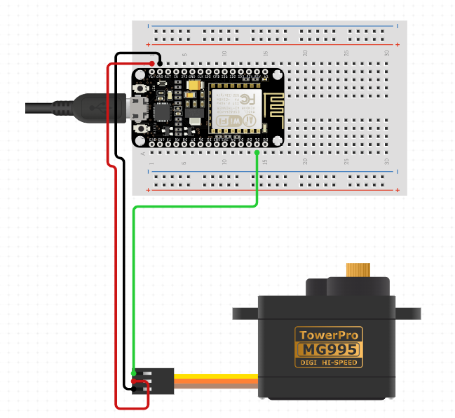
Connect the power supply: Most servo motors operate at 5V DC. Connect the positive (+) and negative (-) wires of the power supply to the corresponding pins on the servo motor.
Connect the control signal: The control signal is a PWM (Pulse Width Modulation) signal that tells the servo motor the angle it should rotate to. Connect the control wire of the servo motor to one of the PWM pins on the Arduino board (e.g. Pin 9).
Write the code: Use the Servo library in Arduino to control the servo motor. The code below demonstrates how to rotate the servo motor from 0 degrees to 180 degrees and back to 0 degrees with a delay of 30 milliseconds between each step:
        #include <Servo.h>
        Servo myservo;  // create servo object to control a servo
        void setup() {
          myservo.attach(9);  // attaches the servo on pin 9 to the servo object
        }
        void loop() {
          for (int pos = 0; pos <= 180; pos += 1) {  // goes from 0 degrees to 180 degrees
            myservo.write(pos);                      // tell servo to go to position in variable 'pos'
            delay(30);                               // waits 30ms for the servo to reach the position
          }
          for (int pos = 180; pos >= 0; pos -= 1) {  // goes from 180 degrees to 0 degrees
            myservo.write(pos);                      // tell servo to go to position in variable 'pos'
            delay(30);                               // waits 30ms for the servo to reach the position
          }
        }
The servo motor should now rotate back and forth between 0 degrees and 180 degrees. You can adjust the delay time and angle range to suit your needs.
NOTE:you can also use a servo motor to move it at a fixed degree
          #include <Servo.h>
          Servo myservo;  // create servo object to control a servo
          void setup() {
            myservo.attach(9);  // attaches the servo on pin 9 to the servo object
          }
          void loop() {
            myservo.write(90);  // moves the servo to 90 degrees
            delay(1000);        // waits for the servo to reach the position}
The loop() function is used to continuously run the code, and in this case, it moves the servo to 90 degrees and waits for 1 second before repeating the process. You can change the angle to any degree you want by modifying the value inside the write() method.
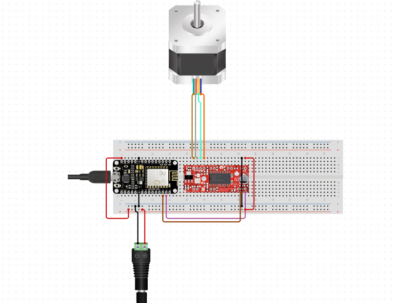
Using a Steppar Motor with Arduino
Connect the stepper motor to your Arduino: Stepper motors have four or five wires, which you need to connect to the corresponding pins on the Arduino. The exact wiring will depend on the type of stepper motor you have, but you can usually find a wiring diagram online. You will also need to connect a power supply to the motor.
Include the Stepper Library: Before you can control the stepper motor, you need to include the Stepper Library in your Arduino sketch. To do this, go to Sketch > Include Library > Stepper.
Define the Stepper Object: In your sketch, you need to define a Stepper object that tells the Arduino which pins are connected to the motor. The syntax for this is as follows:
Replace stepsPerRevolution with the number of steps your stepper motor takes to make one complete revolution, and replace pin1, pin2, pin3, and pin4 with the pins connected to the stepper motor.
Set the Speed: You can set the speed of the stepper motor using the setSpeed() method of the Stepper object. For example, to set the speed to 100 rpm, you would use the following code snippet.
myStepper.setSpeed(100);
Control the Stepper Motor: To move the stepper motor, you need to call the step() method of the Stepper object. This method takes one parameter, which is the number of steps you want the motor to take.
          #include <Stepper.h>
          const int stepsPerRevolution = 200; // change this to fit the number of steps per revolution
          const int motorPin1 = 2;           // connect pin 2 to IN1 on the ULN2003 driver
          const int motorPin2 = 3;           // connect pin 3 to IN2 on the ULN2003 driver
          const int motorPin3 = 4;           // connect pin 4 to IN3 on the ULN2003 driver
          const int motorPin4 = 5;           // connect pin 5 to IN4 on the ULN2003 driver
          Stepper myStepper(stepsPerRevolution, motorPin1, motorPin2, motorPin3, motorPin4);
          void setup() {
            // set the speed at 60 rpm:
            myStepper.setSpeed(60);
          }
          void loop() {
            // step one revolution in one direction:
            myStepper.step(stepsPerRevolution);
            delay(500);
            // step one revolution in the other direction:
            myStepper.step(-stepsPerRevolution);
            delay(500);
          }
Ultrasonic sensor
An ultrasonic sensor is a type of sensor that uses sound waves with high frequency to measure the distance between the sensor and an object. The sensor sends out sound waves and measures the time taken for the waves to bounce back after hitting the object. This information can be used to calculate the distance between the sensor and the object. Ultrasonic sensors are commonly used in automation, robotics, and security systems, among other applications. They can be used to detect the presence or absence of objects, measure the distance between objects, and determine the level of liquid in a tank. Ultrasonic sensors come in various types, including through-beam, reflective, and proximity sensors.
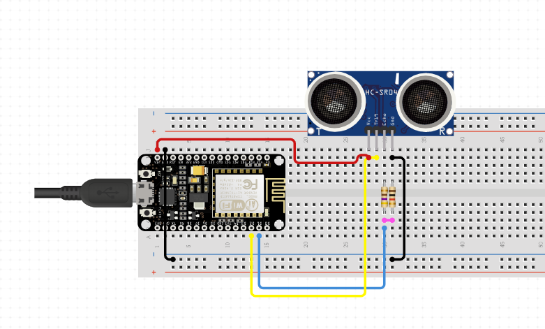
Using ultrasonic sensor with microcontroller
Connect the ultrasonic sensor to the Arduino board using jumper wires. The sensor typically has four pins: VCC, GND, TRIG, and ECHO. Connect VCC to the 5V pin of the Arduino, GND to the GND pin, TRIG to any digital pin (e.g. pin 7), and ECHO to another digital pin (e.g. pin 6).
Write the code for the Arduino board using the Arduino IDE. Here is a sample code to get the distance measurement from the ultrasonic sensor
    const int trigPin = 7; // TRIG pin of ultrasonic sensor connected to digital pin 7
    const int echoPin = 6; // ECHO pin of ultrasonic sensor connected to digital pin 6
    void setup() {
      pinMode(trigPin, OUTPUT);
      pinMode(echoPin, INPUT);
      Serial.begin(9600); // initialize serial communication at 9600 bits per second
    }
    void loop() {
      digitalWrite(trigPin, LOW); // set TRIG pin to LOW
      delayMicroseconds(2);
      digitalWrite(trigPin, HIGH); // set TRIG pin to HIGH
      delayMicroseconds(10);
      digitalWrite(trigPin, LOW); // set TRIG pin to LOW
      long duration = pulseIn(echoPin, HIGH); // measure the duration of the ECHO pulse
      int distance = duration * 0.034 / 2; // calculate the distance in centimeters
      Serial.print("Distance: ");
      Serial.print(distance);
      Serial.println(" cm");
      delay(500); // wait for half a second before taking another measurement
    }
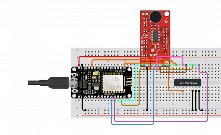
Sound sensor
A sound sensor, also known as a sound module or sound detector, is an electronic module designed to detect the presence of sound and convert it into an electrical signal that can be measured and processed by a microcontroller, such as an Arduino board. Sound sensors are widely used in various applications such as noise pollution monitoring, smart home automation, security systems, and musical instruments.
Sound sensors typically consist of a microphone, an amplifier circuit, and a threshold detection circuit. The microphone captures sound waves and converts them into a small electrical signal, which is then amplified by the amplifier circuit to increase its strength. The threshold detection circuit compares the amplified signal to a preset threshold level and outputs a digital signal based on whether the sound level exceeds the threshold or not.
To use a sound sensor with an Arduino board, you need to connect the sensor's analog output pin to one of the analog input pins of the Arduino board, and the sensor's power and ground pins to the corresponding power and ground pins of the Arduino board. You can then read the sensor's output signal using the analogRead() function in the Arduino IDE, which will return a value between 0 and 1023 representing the sound level detected by the sensor.
    const int soundSensorPin = A0; // Analog input pin for sound sensor
    int soundSensorValue = 0; // Variable to store sound sensor value
    void setup() {
      Serial.begin(9600); // Initialize serial communication
    }
    void loop() {
      soundSensorValue = analogRead(soundSensorPin); // Read sound sensor value
      Serial.print("Sound Level: "); // Print sound level to serial monitor
      Serial.println(soundSensorValue);
      delay(1000); // Wait for 1 second
    }
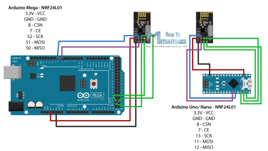
RF transreceiver module
RF (Radio Frequency) transceiver is a device that can both transmit and receive wireless radio signals. It is used to establish wireless communication between two or more devices. The RF transceiver consists of both a transmitter and a receiver that share common circuitry and a common antenna.
RF transceivers can operate on a variety of frequencies depending on the intended application, and the most commonly used frequencies for RF communication are in the range of 315 MHz, 433 MHz, 2.4 GHz, and 5.8 GHz. They are widely used in a variety of applications, such as wireless communication systems, remote controls, wireless sensors and networks, and satellite communications.
In Arduino projects, RF transceivers are often used to establish wireless communication between different devices, such as sensors, actuators, and microcontrollers. By using RF transceivers, data can be transmitted wirelessly over a short distance, enabling the development of wireless control systems, home automation, and IoT (Internet of Things) applications.
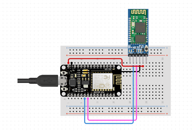
Bluetooth module in Arduino is a wireless communication module that enables the Arduino board to communicate with other Bluetooth-enabled devices such as smartphones, laptops, tablets, and other Arduino boards. The module allows the Arduino board to send and receive data wirelessly over a short distance using Bluetooth technology.
There are various Bluetooth modules available that can be used with Arduino, such as HC-05, HC-06, HM-10, and so on. These modules work on the Serial Protocol and can be connected to the RX and TX pins of the Arduino board. Once the connection is established, the module can be used to send and receive data wirelessly.
To use a Bluetooth module with Arduino, we need to follow these steps
Connect the Bluetooth module to the Arduino board by connecting the RX and TX pins of the module to the TX and RX pins of the Arduino, respectively.
Connect the VCC and GND pins of the module to the 5V and GND pins of the Arduino, respectively.
Upload the sketch to the Arduino board that reads and writes data using the Serial Protocol.
Pair the Bluetooth module with the device you want to communicate with.
Open the Serial Monitor on the device and start sending/receiving data wirelessly.
    #include <SoftwareSerial.h>
    SoftwareSerial BTSerial(10, 11); // RX, TX pins of Bluetooth module
    void setup() {
      Serial.begin(9600);
      BTSerial.begin(9600); // Default baud rate of Bluetooth module
    }
    void loop() {
      if (BTSerial.available()) { // Check if data is available from Bluetooth module
        Serial.write(BTSerial.read()); // Send data received from Bluetooth module to Serial Monitor
      }
      if (Serial.available()) { // Check if data is available from Serial Monitor
        BTSerial.write(Serial.read()); // Send data received from Serial Monitor to Bluetooth module
      }}
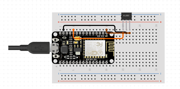
Hall effect Sensor
A Hall effect sensor is a type of magnetic sensor that detects changes in magnetic fields. It is named after Edwin Hall, an American physicist who discovered the effect in 1879. The sensor consists of a thin sheet of semiconducting material, such as indium arsenide or gallium arsenide, with a small strip of metal on top. When a magnetic field is applied perpendicular to the surface of the material, a voltage is generated across the metal strip. This voltage is proportional to the strength of the magnetic field.
Hall effect sensors are commonly used in electronic devices to measure magnetic fields and to detect the position, velocity, and direction of moving objects. They are also used in automotive and industrial applications, such as speed and position sensors, and in electronic compasses.
To use a Hall effect sensor with an Arduino, you can connect the sensor's output pin to an analog input pin on the Arduino. The analog input pin will read the voltage generated by the sensor and convert it into a digital value that can be used by the Arduino.
    int hallPin = A0; // connect sensor output pin to analog pin A0
    void setup() {
      Serial.begin(9600); // initialize serial communication
    }
    void loop() {
      int sensorValue = analogRead(hallPin); // read sensor value
      Serial.println(sensorValue); // print sensor value to serial monitor
      delay(100); // wait for 100ms before taking another reading
    }
we define the analog input pin connected to the Hall effect sensor as hallPin. In the setup() function, we initialize serial communication at a baud rate of 9600. In the loop() function, we read the sensor value using the analogRead() function and store it in the sensorValue variable. We then print the sensor value to the serial monitor using the Serial.println() function and wait for 100ms before taking another reading using the delay() function.
Note that the actual value of the sensor reading will depend on the strength of the magnetic field being detected and the sensitivity of the sensor. You may need to adjust the code and/or the position of the sensor to get accurate readings.
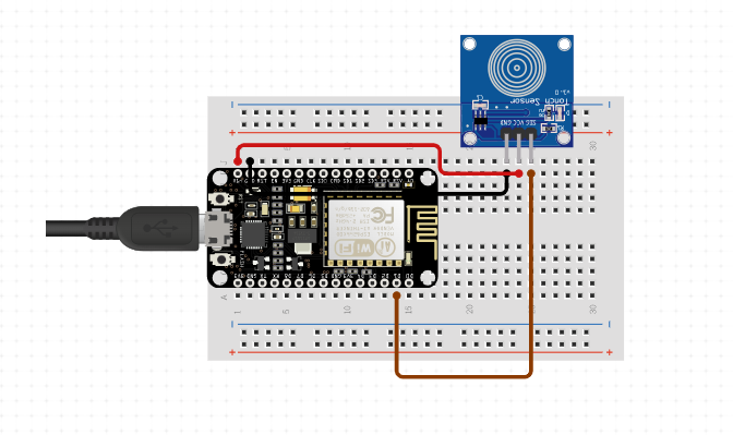
Touch sensor
A touch sensor is a type of sensor that detects physical touch or contact. It is a simple switch that is activated by touching it with a finger or any other conductive material. In Arduino, touch sensors are commonly used to create user interfaces or input systems for various projects.
There are two main types of touch sensors: capacitive touch sensors and resistive touch sensors. Capacitive touch sensors work by detecting changes in capacitance when an object comes in contact with the sensor. Resistive touch sensors work by detecting changes in resistance when an object comes in contact with the sensor.
To use a touch sensor with Arduino, you first need to choose the appropriate type of sensor and wire it to the Arduino board. Then, you need to write a code that reads the state of the touch sensor and performs some action based on the input.
For example, you can use a capacitive touch sensor to control the brightness of an LED by increasing or decreasing the capacitance of the sensor. Alternatively, you can use a resistive touch sensor to create a simple game or interactive interface where the user has to touch the screen to perform some action.
    #include <CapacitiveSensor.h>
    const int touchPin = 2; // the pin number of the touch sensor
    const int ledPin = 9; // the pin number of the LED
    const int threshold = 1000; // the threshold value for touch detection
    CapacitiveSensor cs = CapacitiveSensor(2, 4); // initialize the touch sensor
    void setup() {
      pinMode(ledPin, OUTPUT);
    }
    void loop() {
      long touchValue = cs.capacitiveSensor(30); // read the touch value
      if (touchValue > threshold) { // if the touch value exceeds the threshold
        digitalWrite(ledPin, HIGH); // turn on the LED
      } else {
        digitalWrite(ledPin, LOW); // turn off the LED
      }
      delay(10); // wait for a short period of time
    }
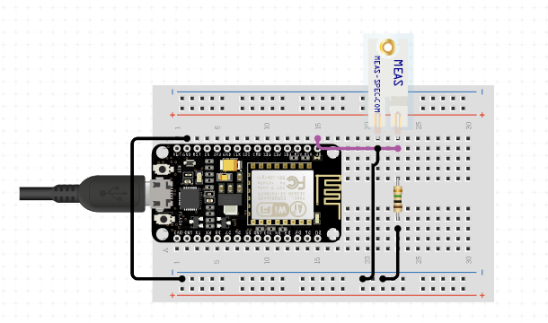
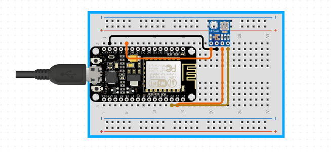
Pressure sensor
Pressure sensors are electronic devices that measure pressure, typically in gases or liquids. They convert the physical pressure into an electrical signal that can be measured and interpreted by electronic circuits, including those built using Arduino microcontrollers.
There are several types of pressure sensors, including piezoelectric, capacitive, and resistive sensors. Piezoelectric sensors use crystals that generate an electrical signal in response to pressure changes, while capacitive sensors measure changes in the capacitance of a circuit due to pressure. Resistive sensors measure changes in resistance, often by using a metal foil or conductive polymer that changes resistance as it is bent or stretched.
To use a pressure sensor with an Arduino, you typically need to connect the sensor to the appropriate pins on the Arduino board and then read the analog or digital signal using the appropriate library and programming code. For example, if you are using an analog pressure sensor, you might connect it to one of the analog input pins on the Arduino and then use the analogRead() function to read the voltage and convert it to a pressure value.
There are many different pressure sensors that are compatible with Arduino boards, ranging from small sensors designed for low-pressure applications to larger sensors that can measure high-pressure fluids and gases.
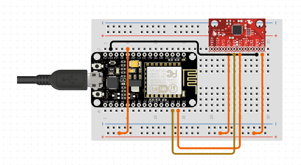
An accelerometer is a sensor that is used to measure acceleration forces. It can measure the acceleration in three directions: forward and backward (X-axis), left and right (Y-axis), and up and down (Z-axis). Accelerometers are commonly used in electronic devices such as smartphones, fitness trackers, and gaming controllers to detect motion and tilt.
There are different types of accelerometers, but the most common ones used with Arduino are based on the Microelectromechanical systems (MEMS) technology. MEMS accelerometers consist of a tiny mass suspended by tiny springs. The mass moves in response to acceleration, and the displacement is measured using piezoelectric or capacitive elements.
To use an accelerometer with Arduino, you need to connect it to the board. Most accelerometers use either the I2C or SPI protocol to communicate with Arduino. Once connected, you can read the acceleration values using Arduino's analog or digital input pins. Some common pressure sensors used with Arduino include the MPU6050, MPU9050, BMP180.